
In this week we learn about designing 2D objects using the software Draftsight and modelling 3D objects using the software Fusion 360 from Autodesk.
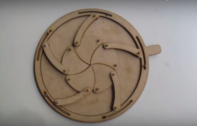
While looking around for inspiration for my 2D Design, I found this cool Mechanical Iris project on Instructable and decided to give it a try. The website also provided the DXF file for the design, thus I started with downloading the file and make some measurements that I find important to "replicate" the design.
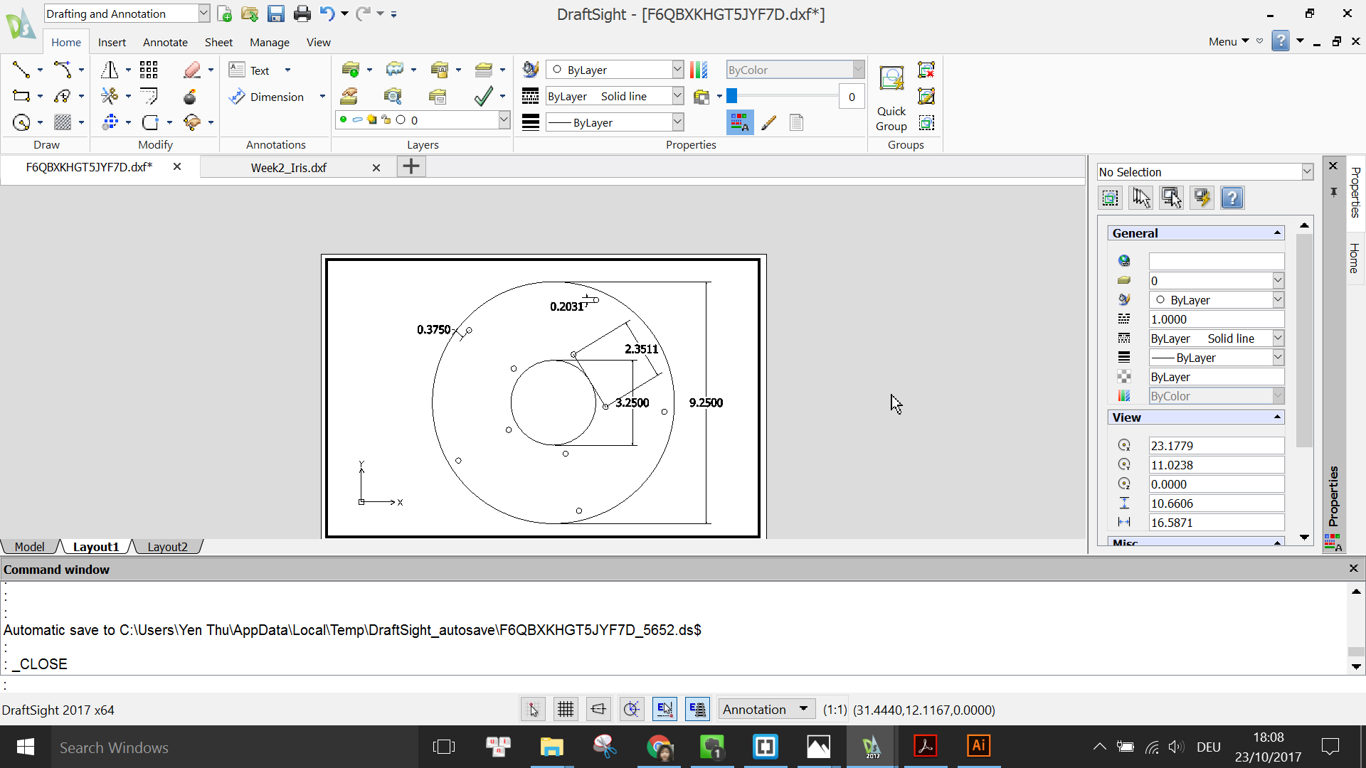
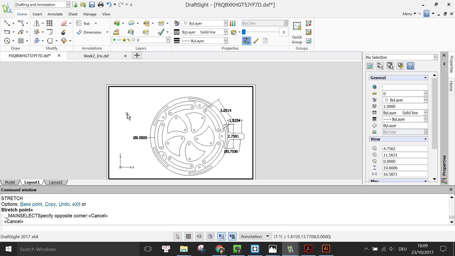
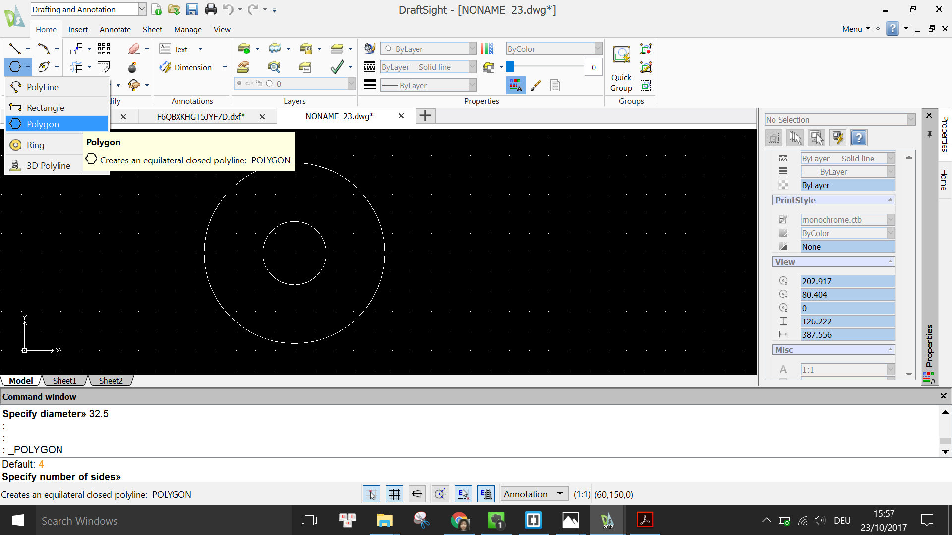
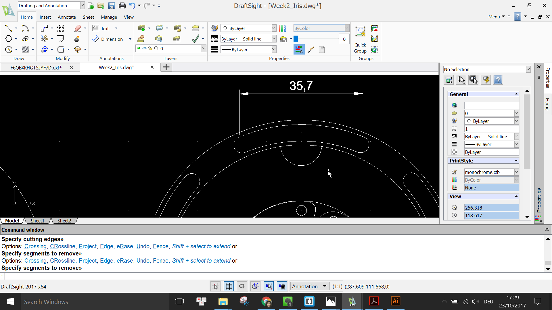
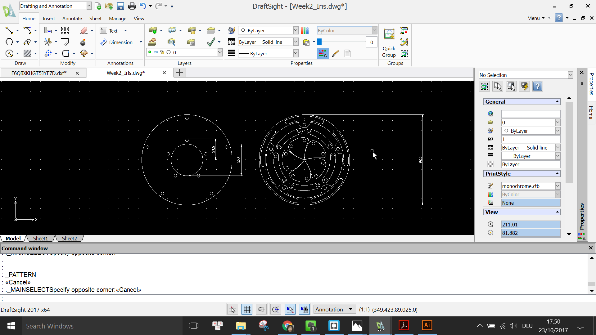
For some reason, the downloaded DXF file is not to the correct scale, as seen from the screenshots above that the design is too small (all measurements are in millimeters). However, this should not be a problem as long as I keep the ratio between the dimensions roughly the same in my design.
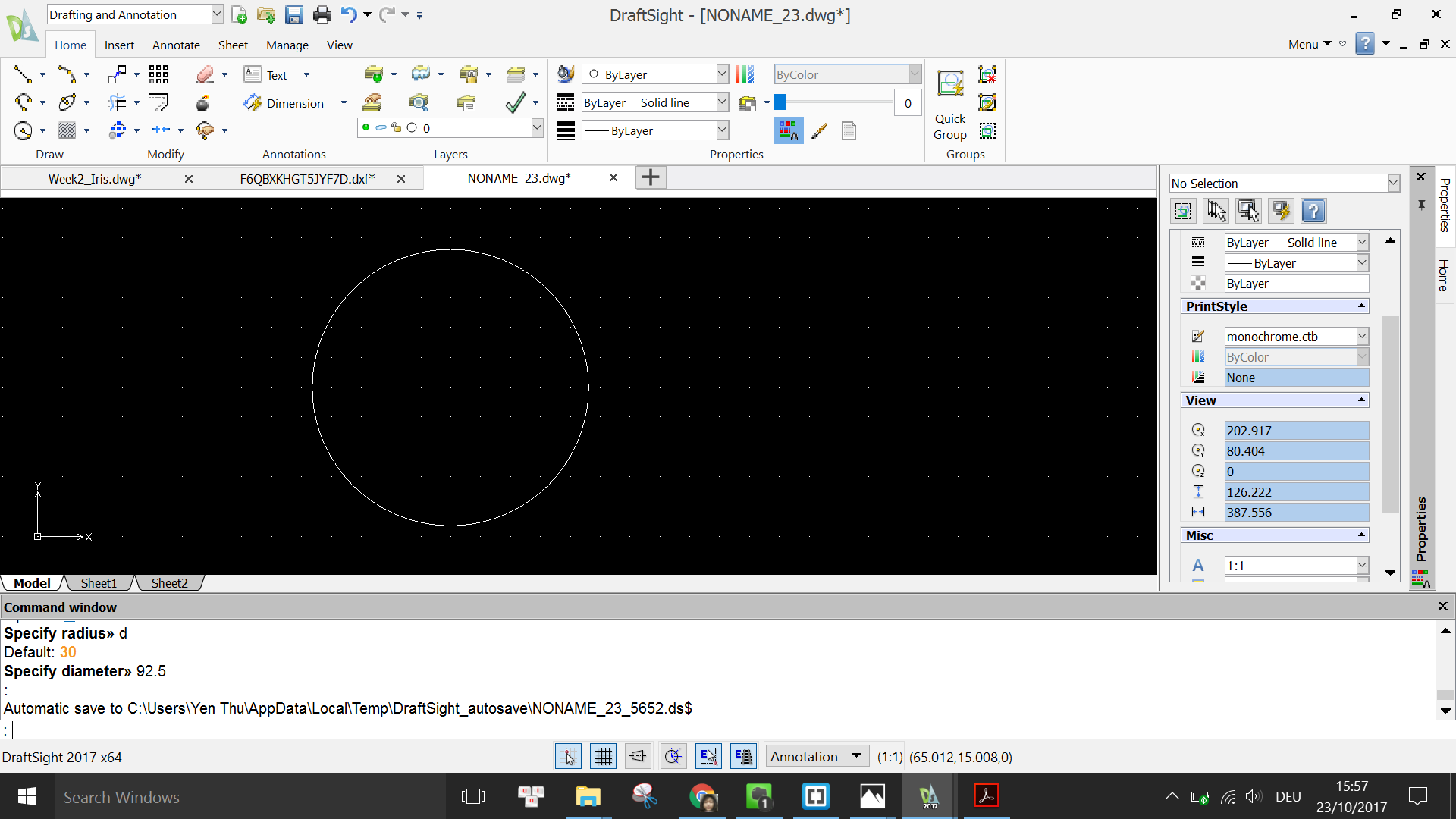
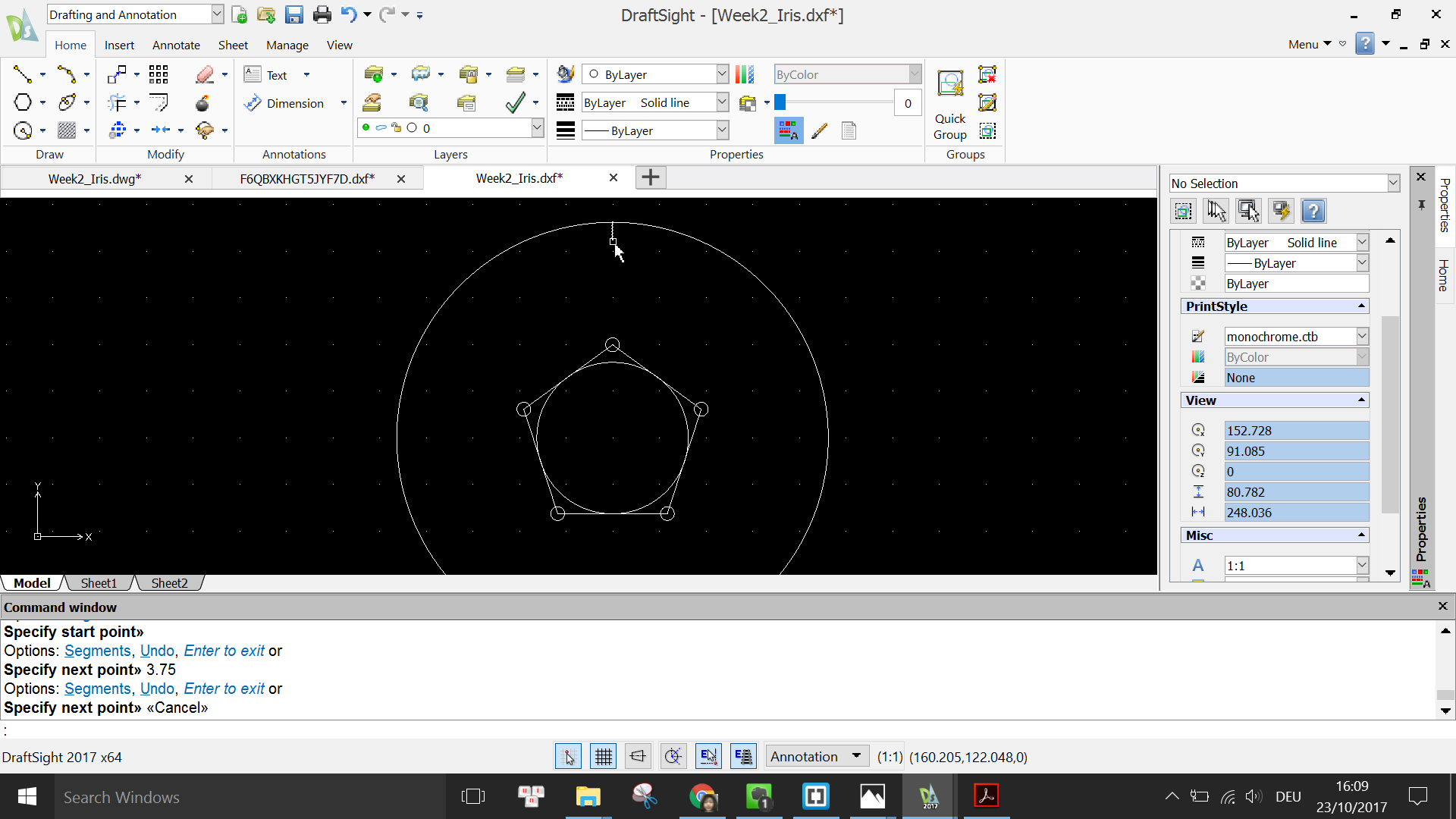
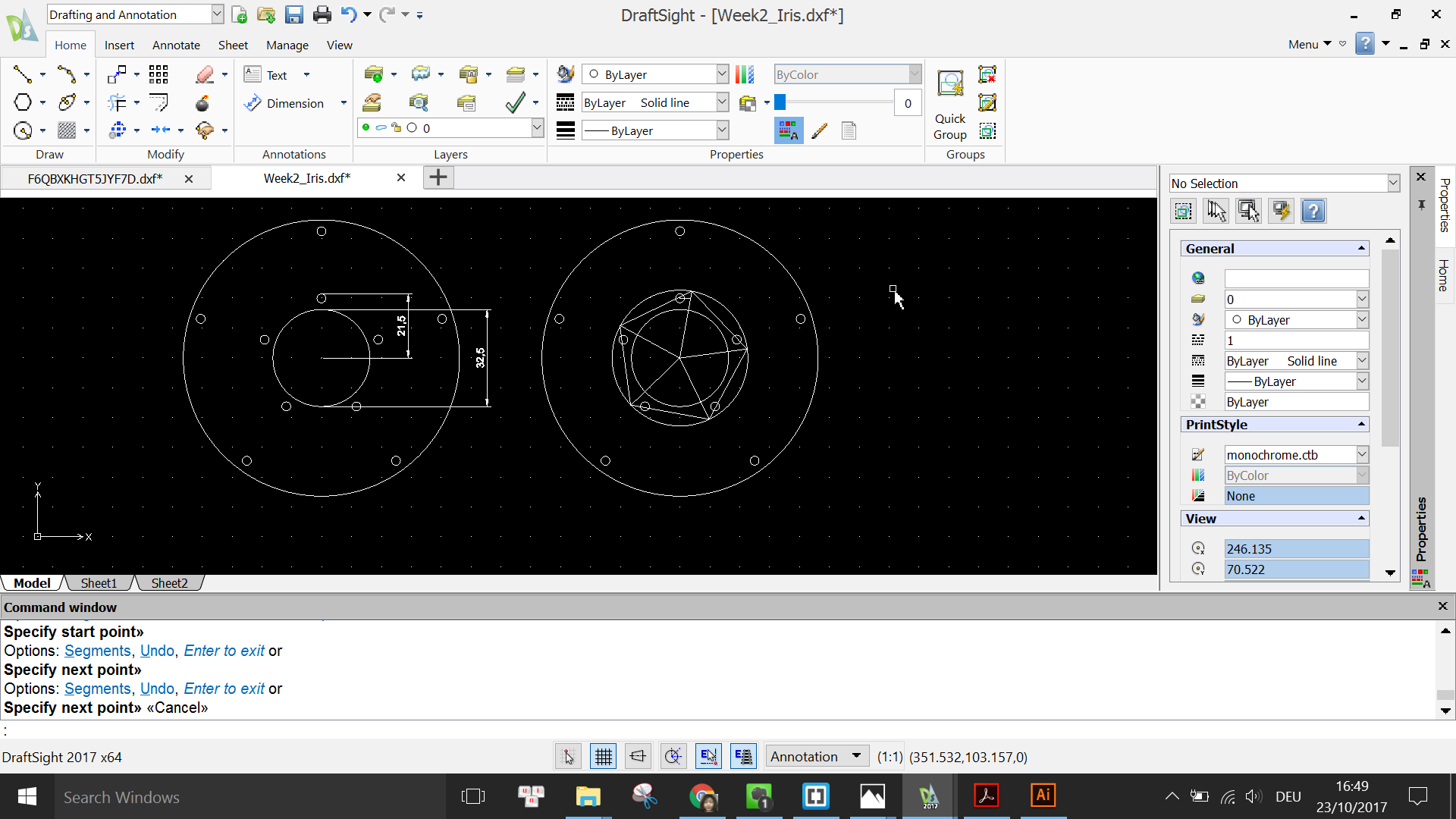
First I turn on the grid by typing in the command window GRID and then ON. Then I start with the simpler part of the design out of the 2. Using the command CIRCLE, I specify a point on the grid to be the center of the circle and enter a diameter of 92.5mm.
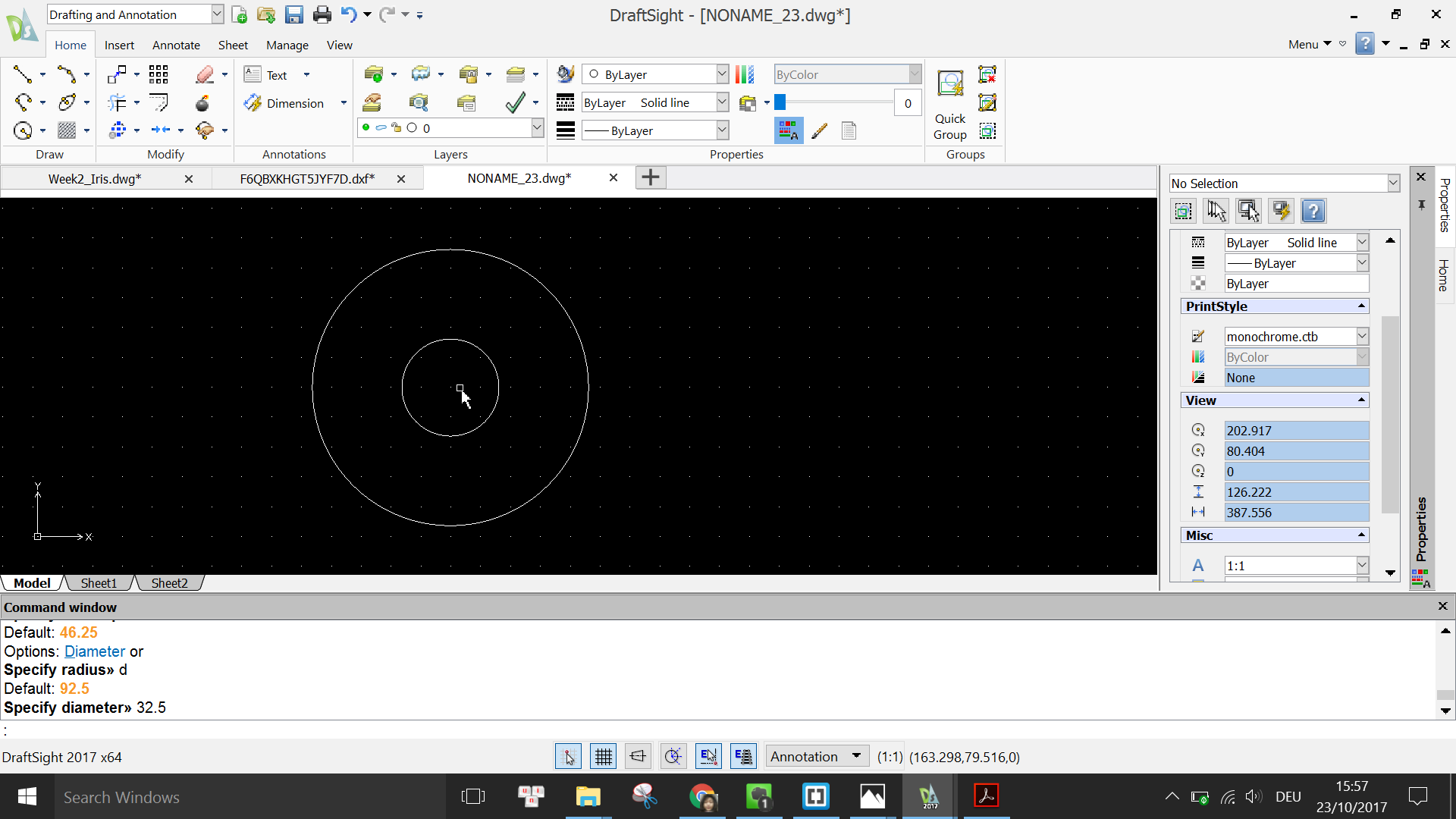
I continue to draw the inner circle using the same command and turn on the E-Snap to pick the same center point as the previous circle, and enter a diameter of 32.5mm.
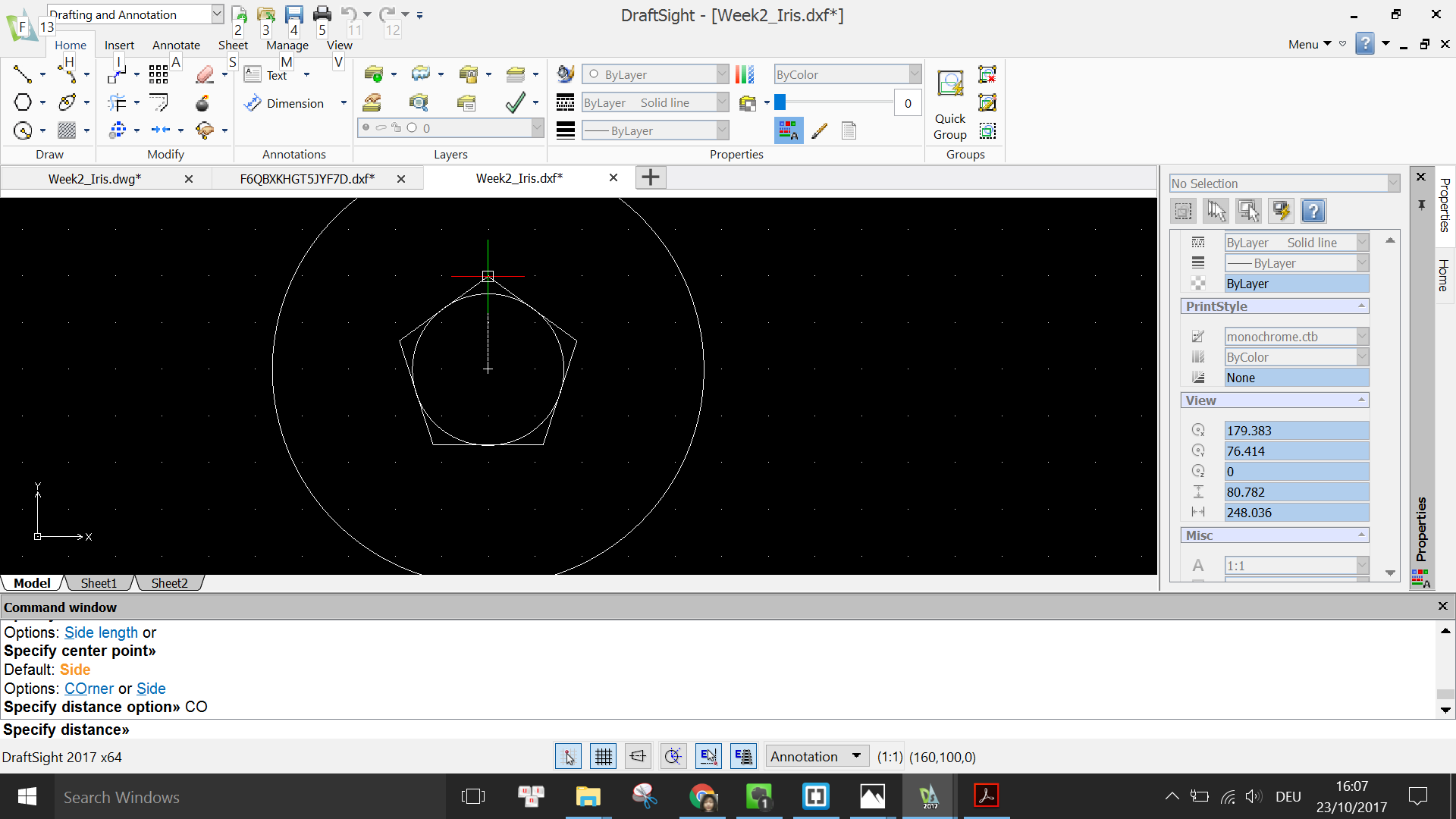
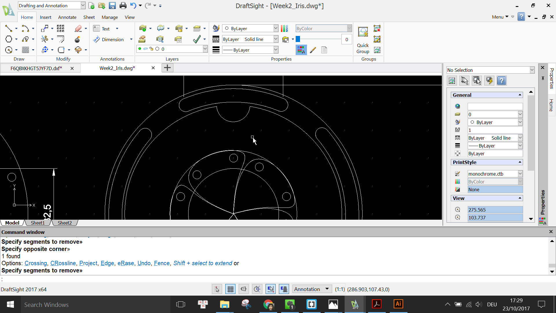
Next, I use the Polygon tool to draw a pentagon by specifying the number of sides to 5, picking the same center point as before, typing in COrner for the option and drag the mouse such that each side of the pentagon just touches the circle.
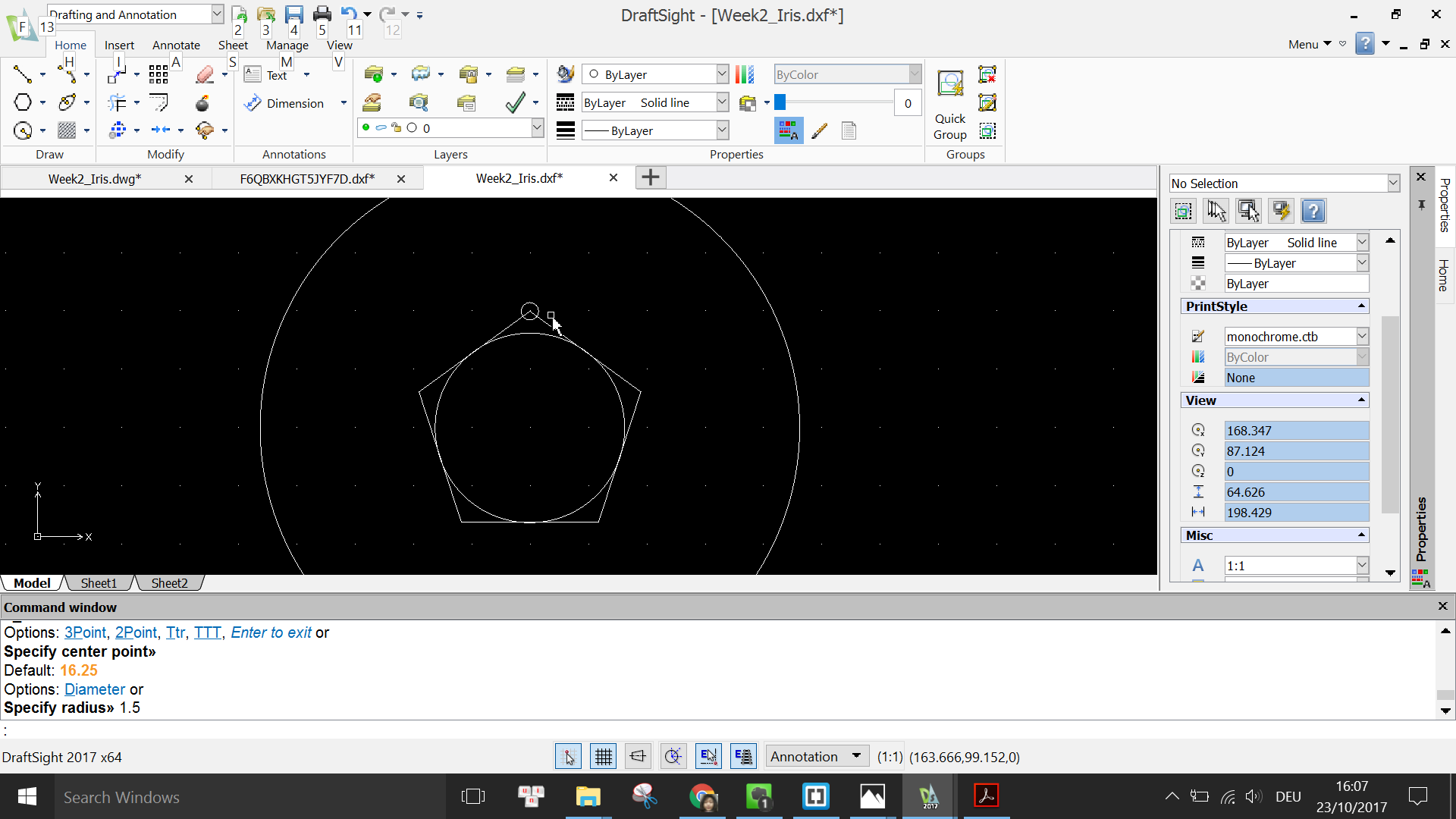
Again I use the CIRCLE command to draw a circle of diameter 3mm whose center lies on one of the vertices of the pentagon. I use 3mm circle because later on I will use 3M screws through the holes.
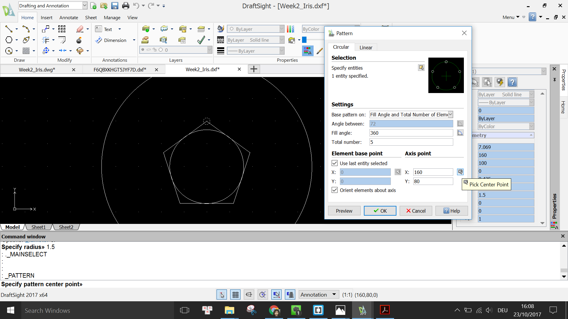
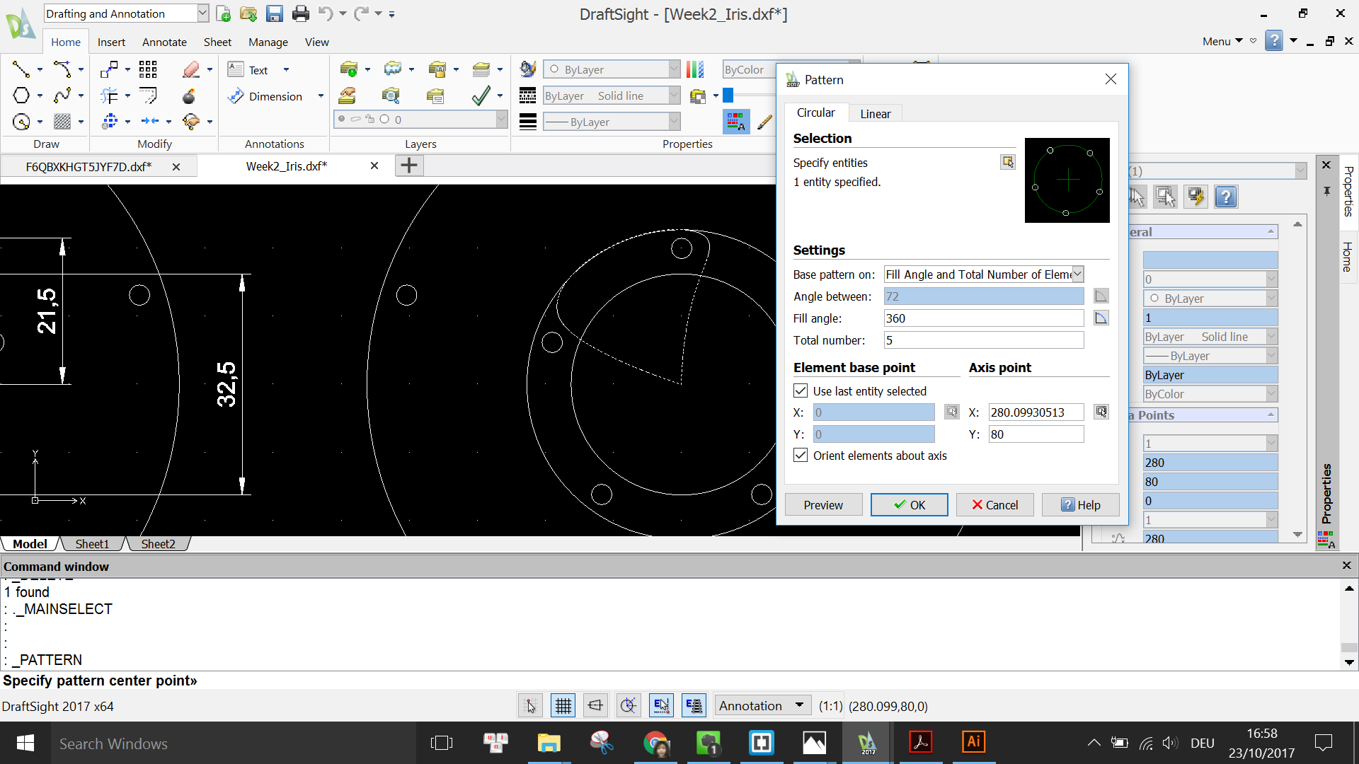
In order to copy the circle to the remaining vertices of the pentagon, I use the PATTERN command. In the pop-up menu, I select the circle as the specified entity, set the Base Pattern on properties to Fill Angle and Total number of Elements so that I can type in the Fill angle = 360° and Total number = 5. Then I select the center point to be the center of the pentagon. By cliking OK, 4 more circles should appear on the other 4 vertices of the pentagon.
Then I draw a line from the top of the circle of size 3.75mm to act as an offset distance for the next sketch.
Using again the POLYGON command with the same options as before, I draw a new concentric pentagon with one of its vertex meeting the end point of the offset line.
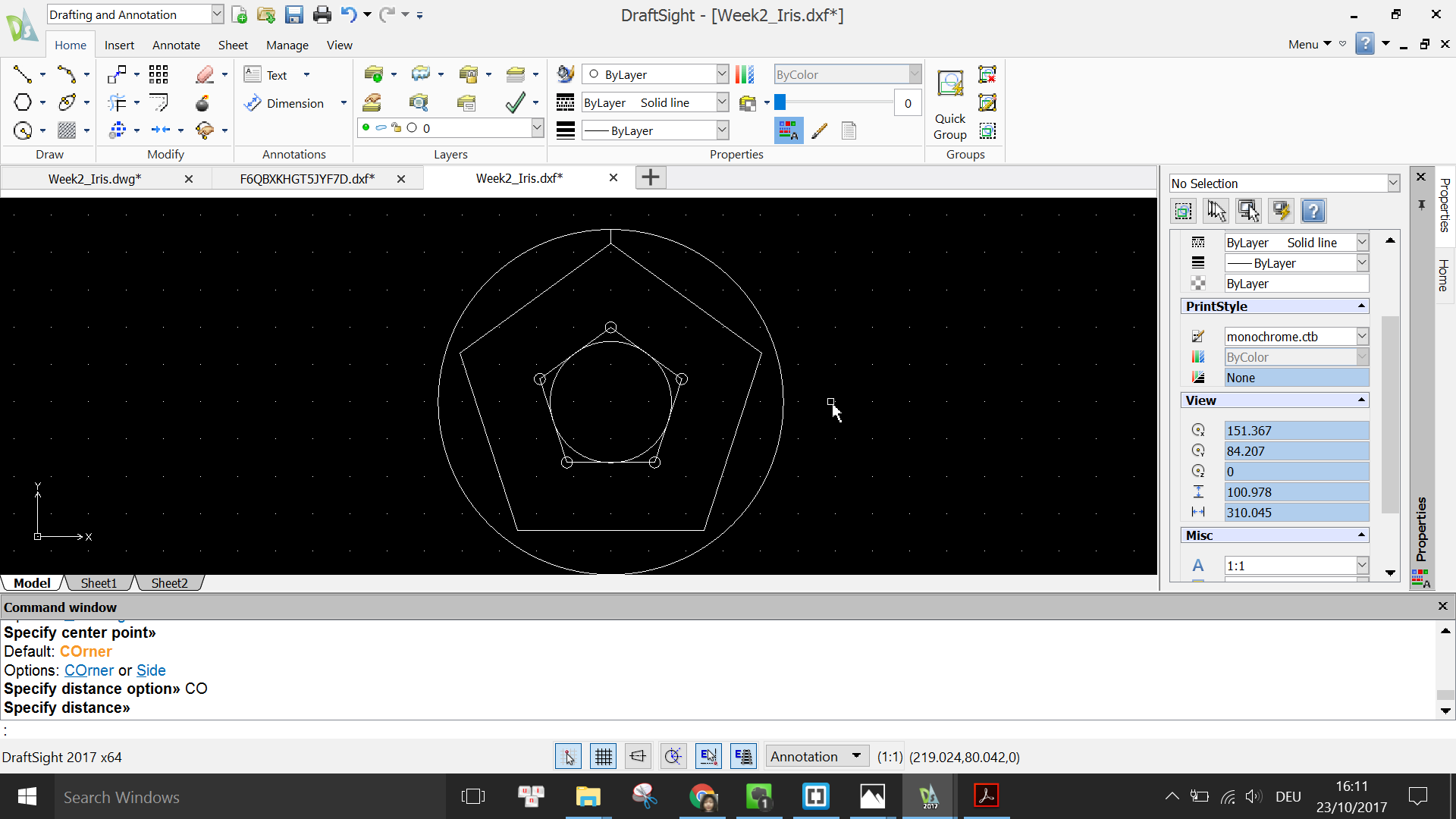
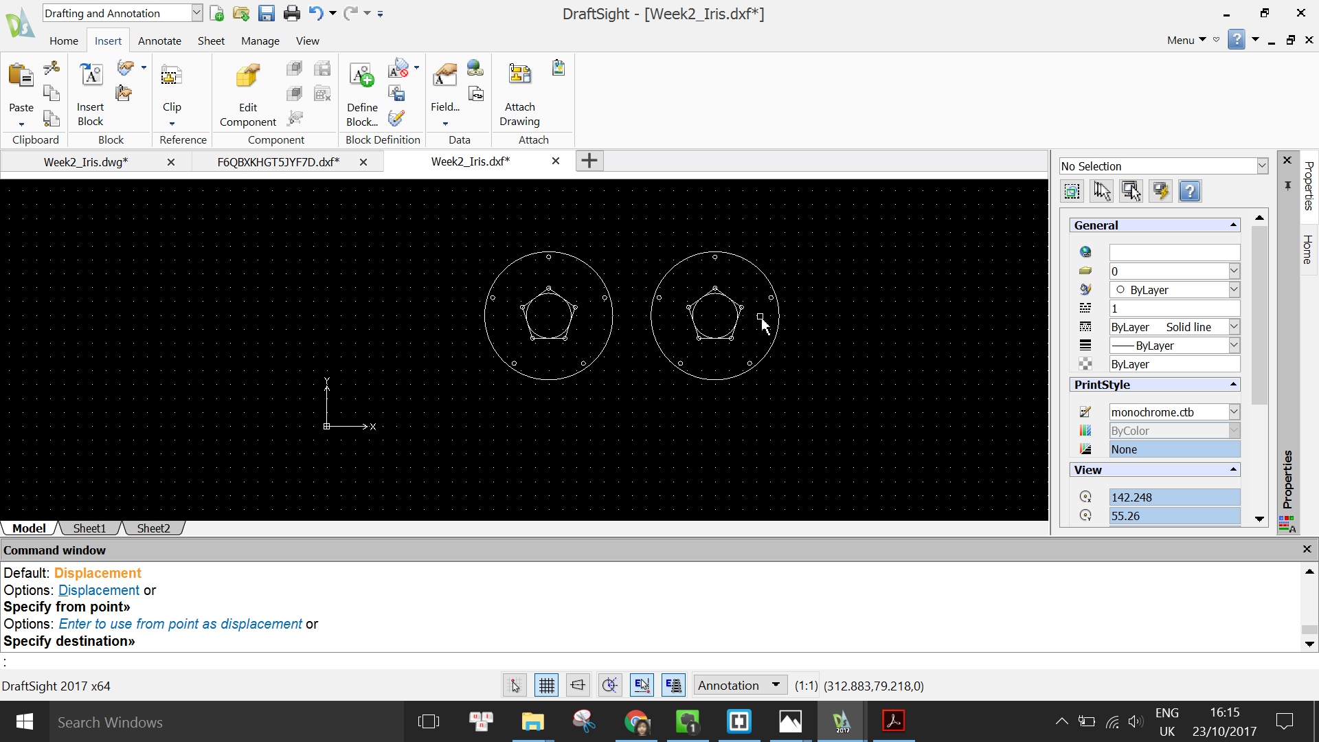
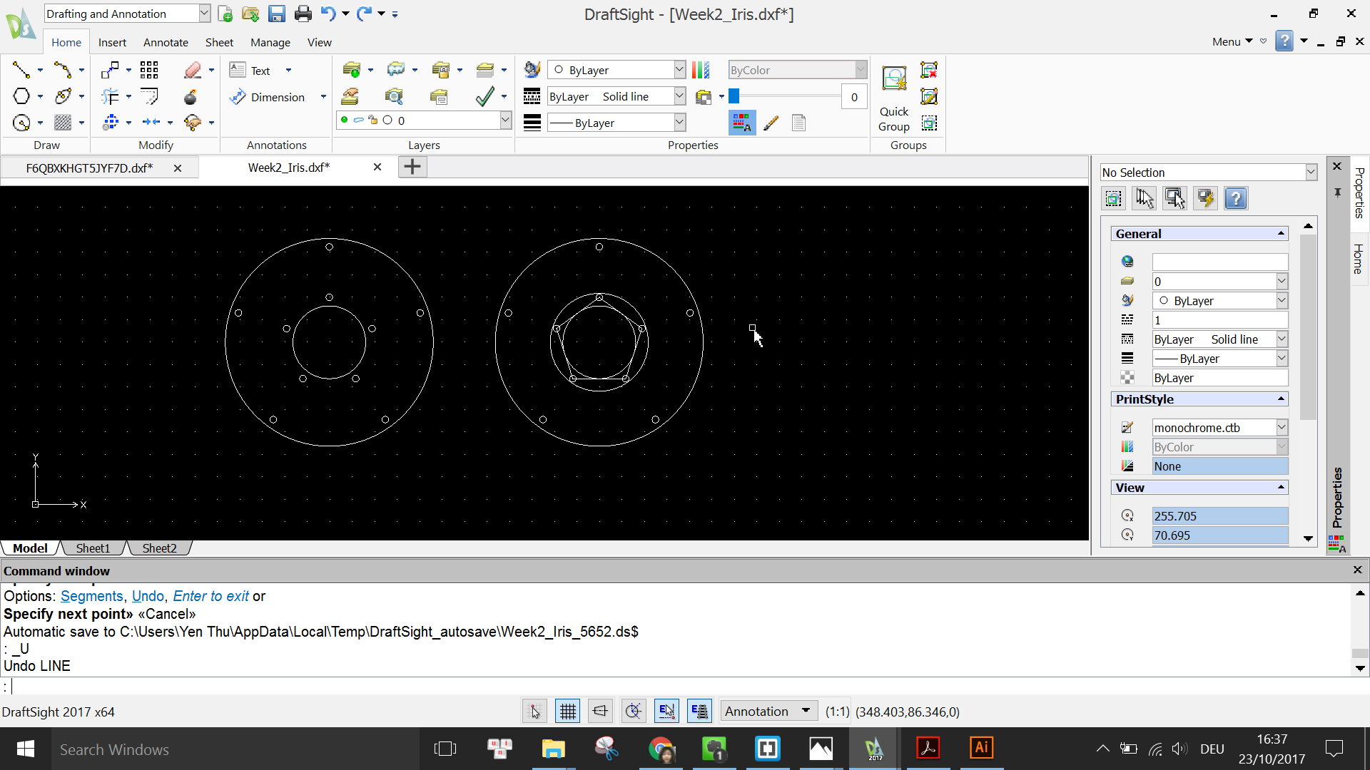
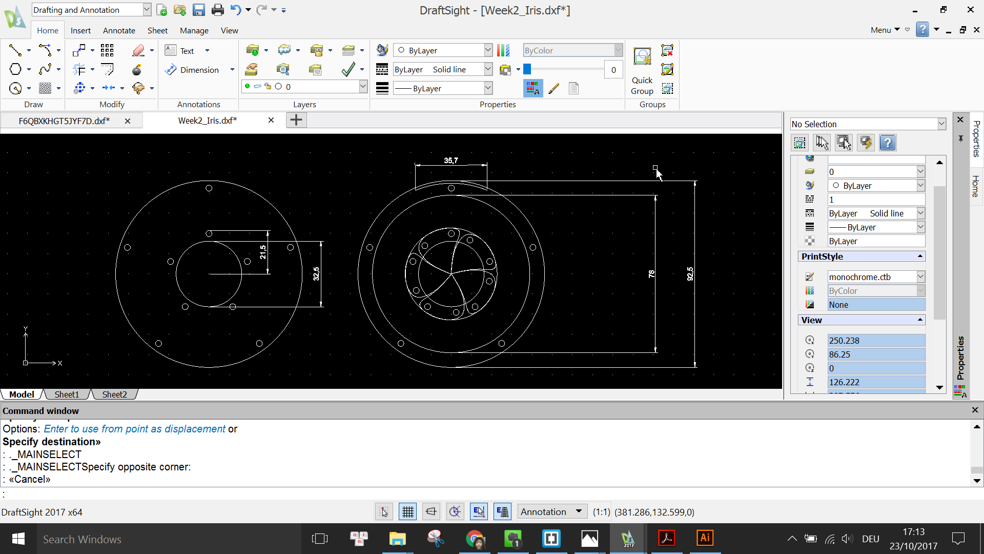
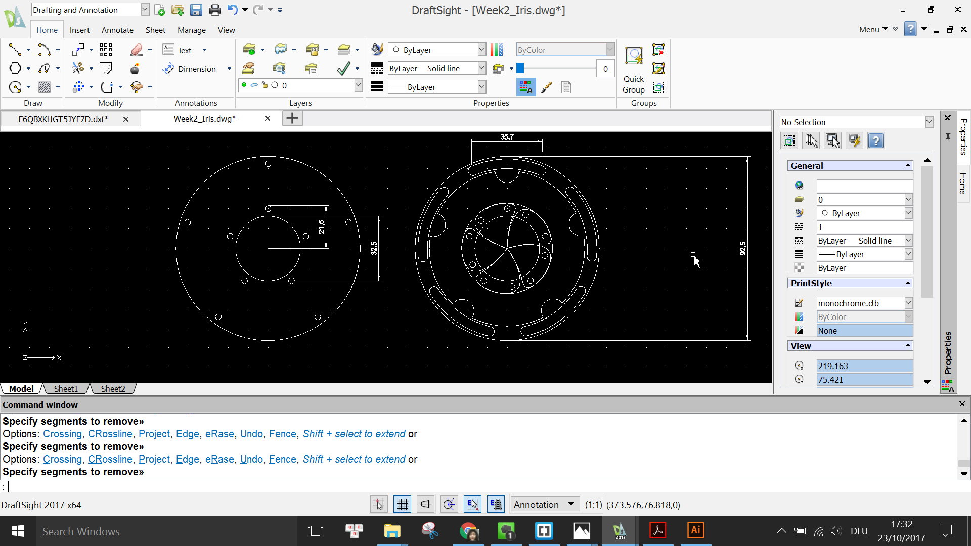
Now that I have finished with the first part of the design, I make a copy of it to use as a guide for the remaining part. Also, I delete the unnecessary elements from the finished part such as the offset distance line and the inner pentagon which was only used to help draw the screw holes.
On the second part of the design now I draw a new circle with the same center and with a radius such that the circle just touches the screw holes.
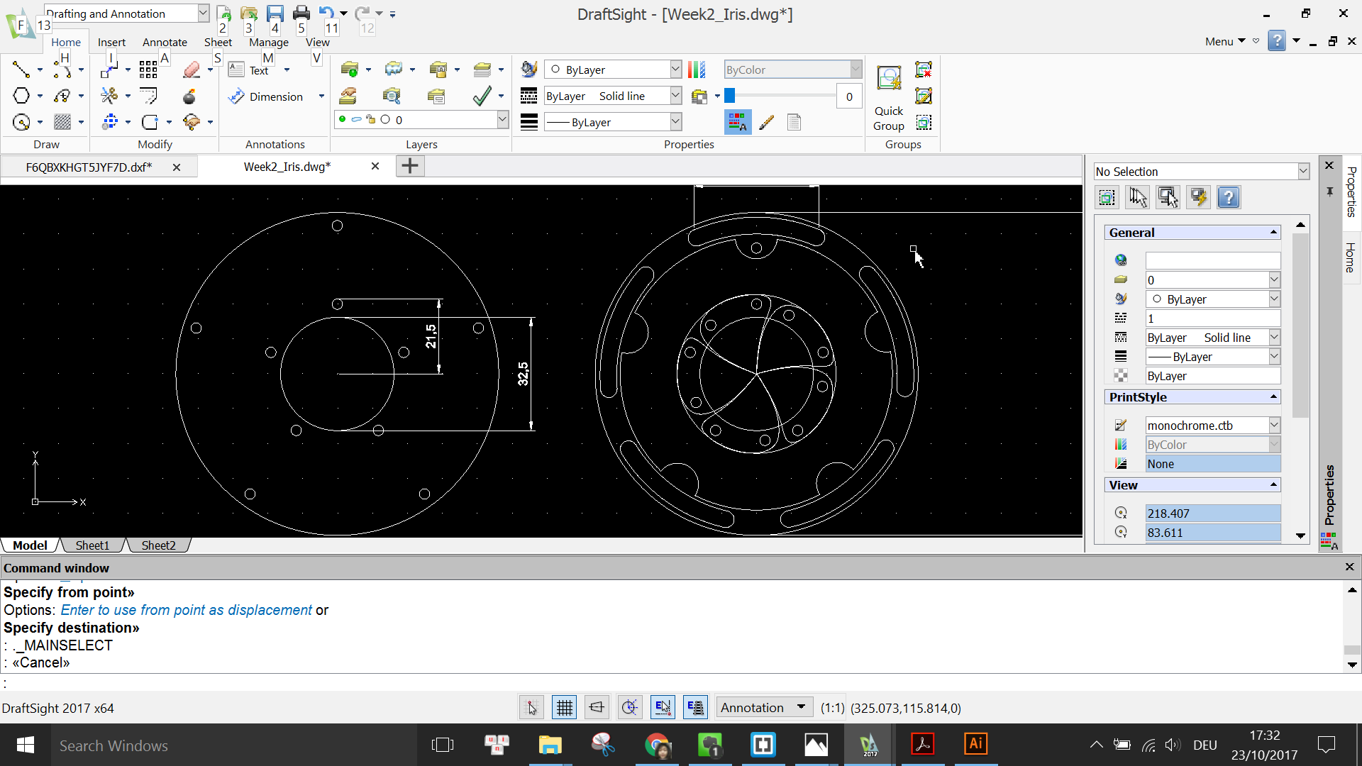
Next I re-check the original design and notice that I have to rotate the inner pentagon, so I use the ROTATE command, choose center of the pentagon as the pivot and use the mouse to drag the pentagon to rotate in a small angle.

Then I draw 5 lines going from the center to the vertices of the pentagon and delete the pentagon because it was only used for reference purpose.

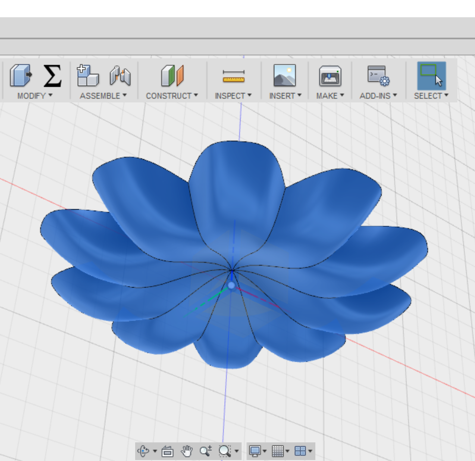
Next, I use the SPLINE tool to draw one "petal" for the Iris using one of the 5 "slices" of the pentagon as a guide.

After having 1 petal, I again type in the PATTERN command to repeat it by 5 times around the center.

Using the CIRCLE command, I draw a new concentric circle with radius of 39mm; and 5 more screw holes inside the "petals". There is no need for the exact position of these new screw holes, as long as they are opposite and roughly in line with the existing screw holes.

Using the ARC command, I draw a small arc above one of the outer screw holes
Then I use the OFFSET command to duplicate the arc with a distance of 4mm below the original one.

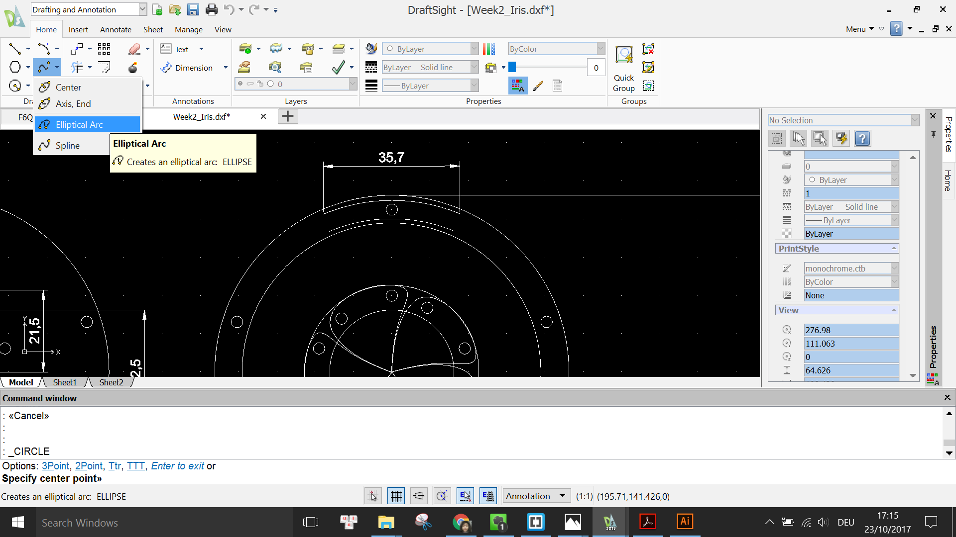
Next I use the Eliptical Arc tool to draw one of the rounded closing ends for the mechanical slot. The radius of the elipse is 2.5mm.
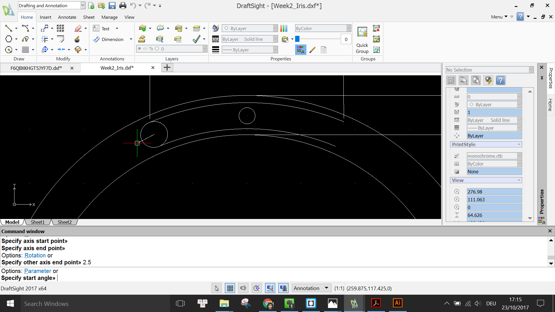

I repeat this step for the other end to finish the mechanical slot
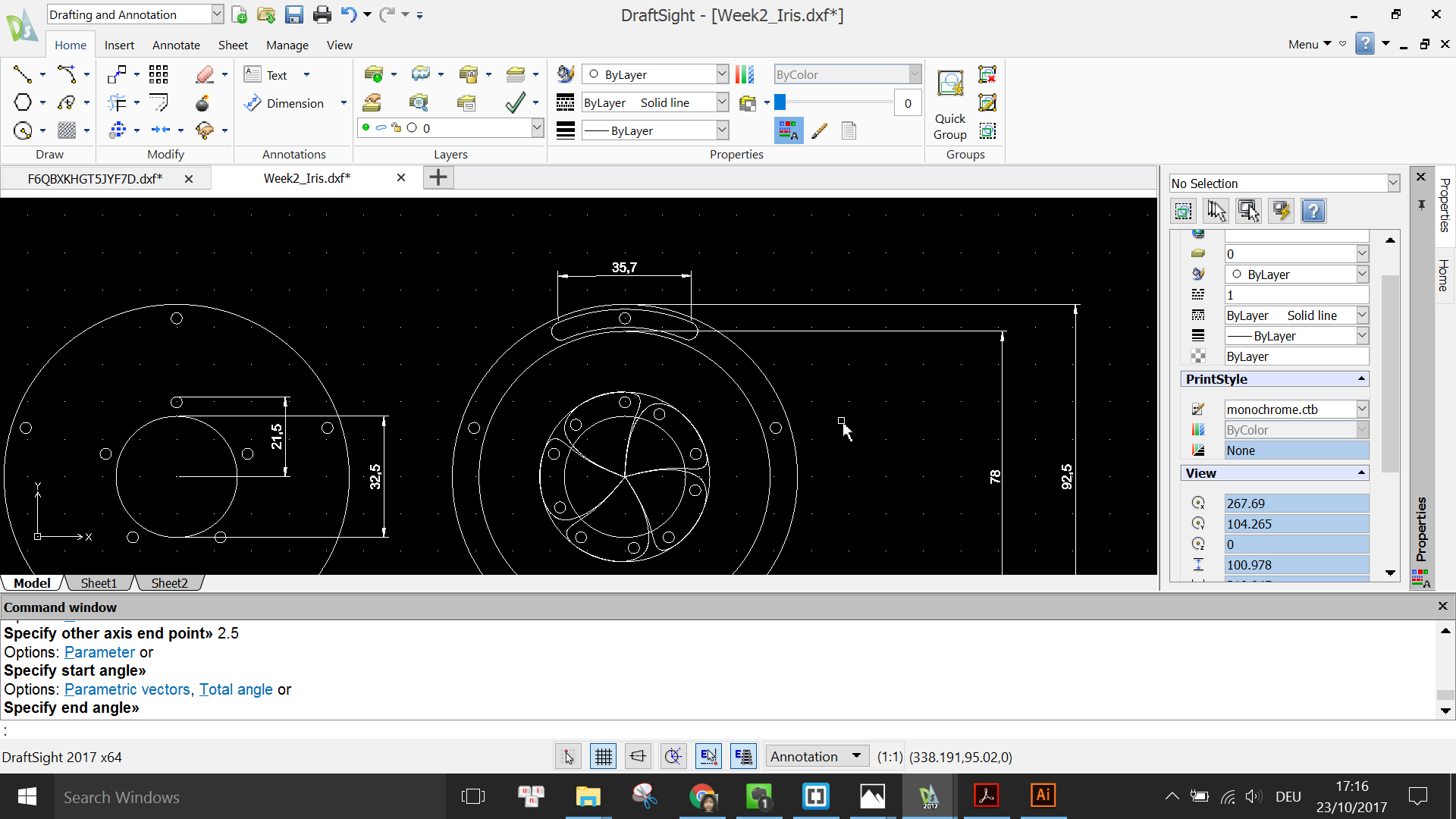
Again, I use the PATTERN command to duplicate it by 5 times around the center.
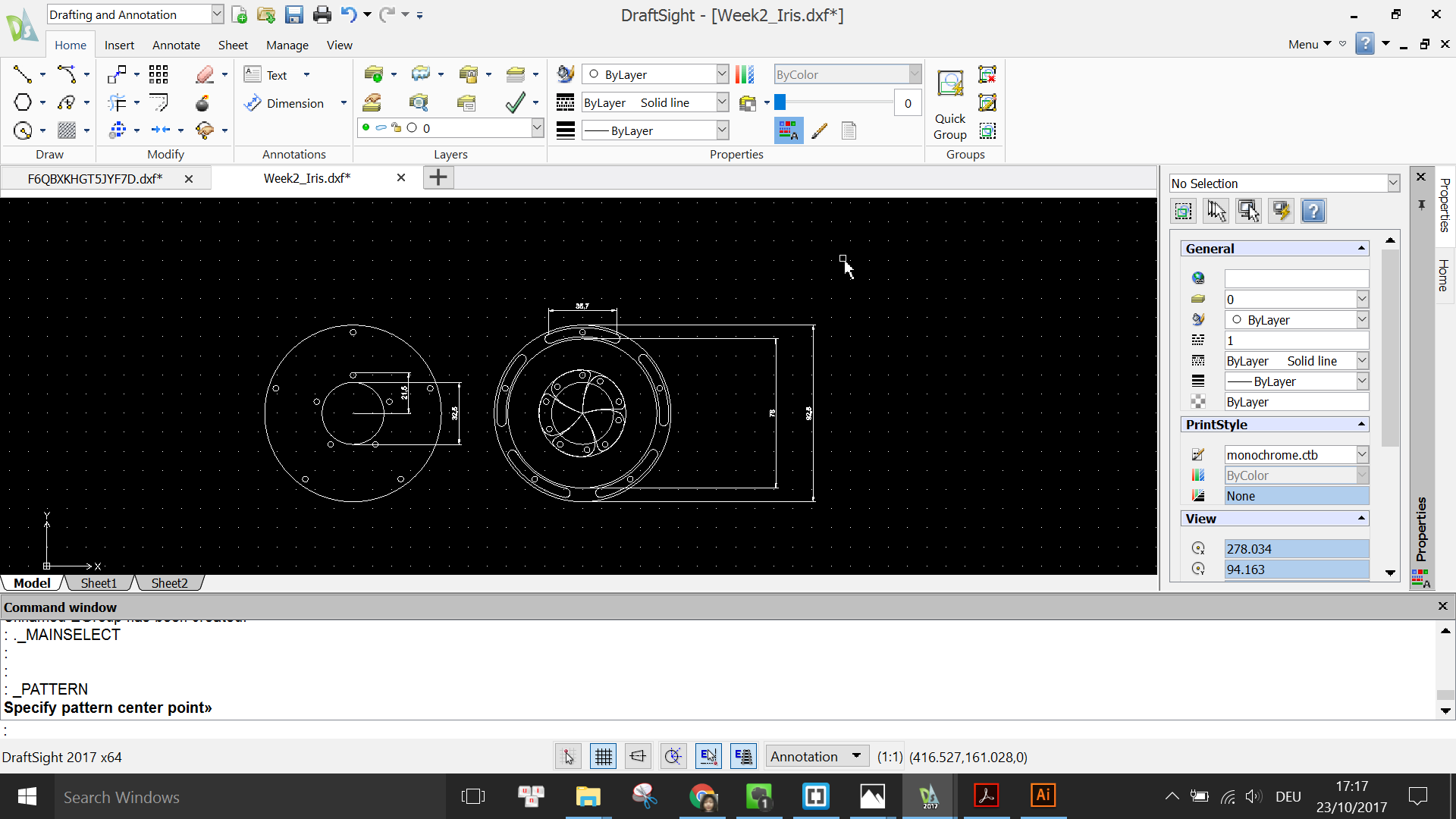
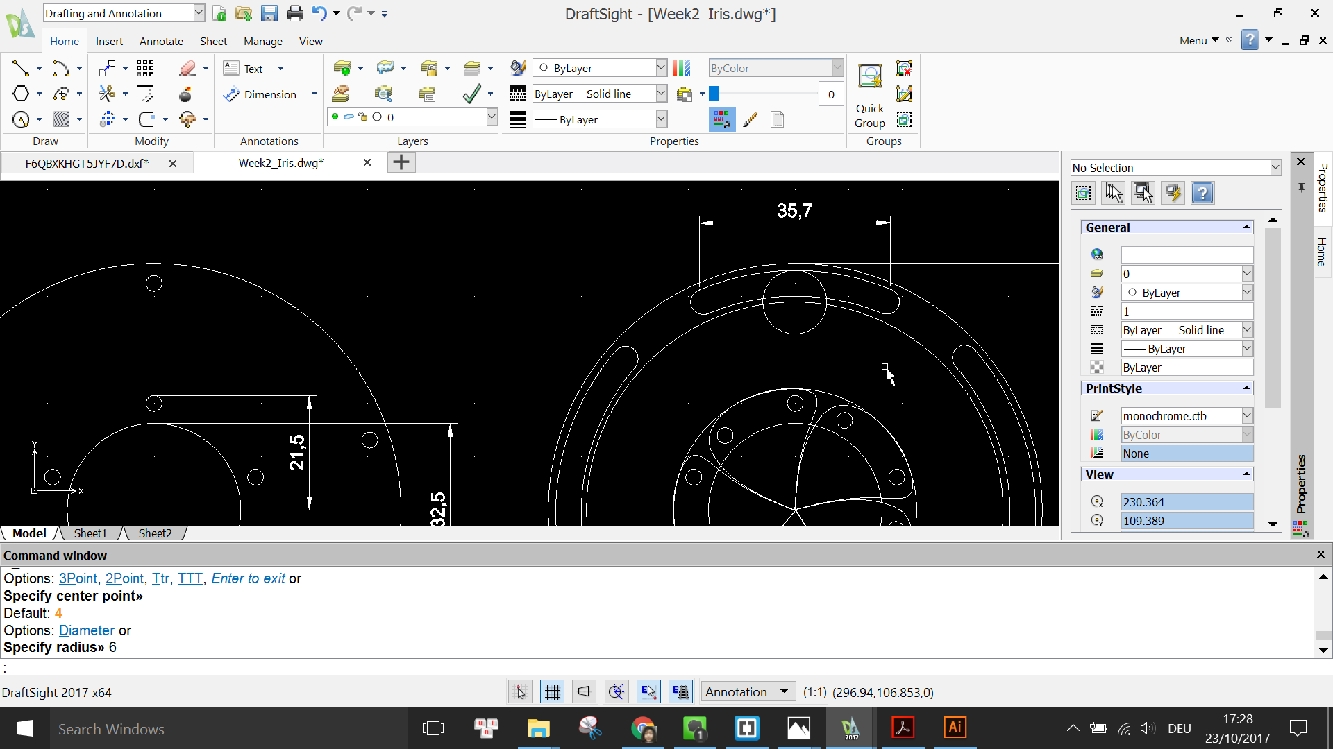
Now I draw a circle of radius 6mm under the slot and use the TRIM tool to remove the unwanted line segments.
Then I repeat the arc again 5 times around the center and trim the unwanted segments for the remaining 4 arcs.

I need to draw 5 more screw holes in the middle of these newly created arcs using the CIRCLE and PATTERN command.
Next I have to create a crank that acts as the connection between the outer frame and the "petal", like in this capture:
To do this, I copy one of the existing mechanical slots, rotate and scale it down using RORATE and SCALE command so that it fits in between the 2 screw holes.

Having the desired sketch of the crank, I copy it and the screw holes and duplicate them 5 times.
Finally, I use the RECTANGLE and CIRCLE tool, as well as the TRIM command to draw the handle for the outer frame.
With that, my design is finished.
Since Halloween is coming soon, I think of making something fun for the holiday. So I looked around Youtube and found this very detailed toturial on How to model a Jack-O-Lantern and decided to follow it. Although I worked with Fusion 360 in the MODEL Environment before, I have never tried working in the SCULPT Environment so I find this tutorial very useful to learn new skills but also quite challenging.
Enough said, let's get started with modelling the Halloween pumpkin.
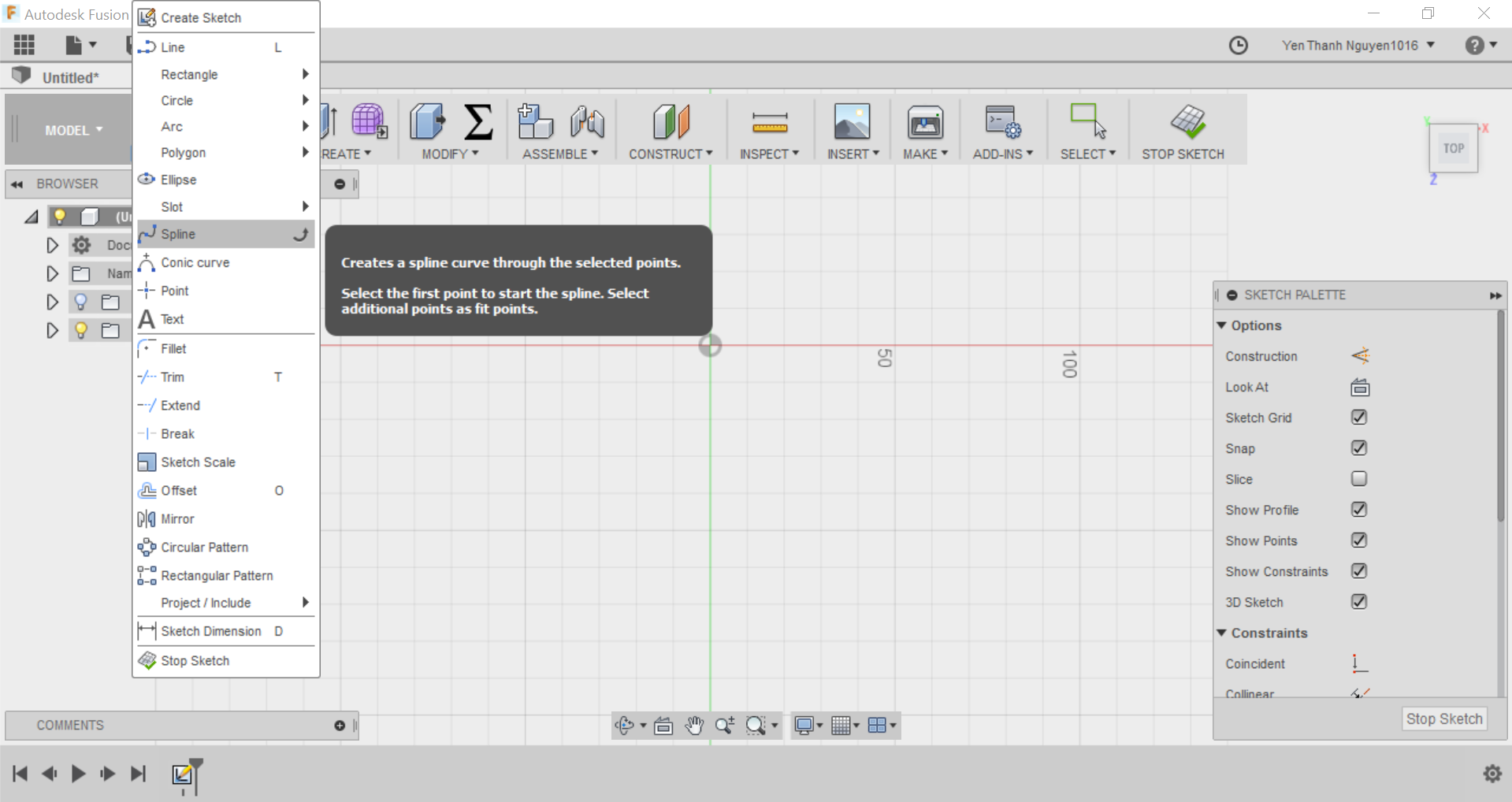
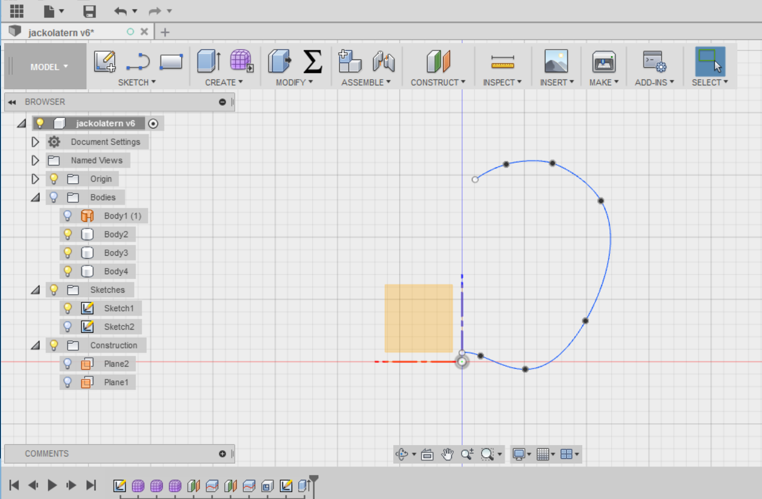
First I create a sketch for the outer shape of the pumpkin. I use the Spline tool under the SKETCH menu and choose the XZ working plane.
I do not have to draw the full outer shape but only half of it because I would like it to be symmetrical about the vertical axis.
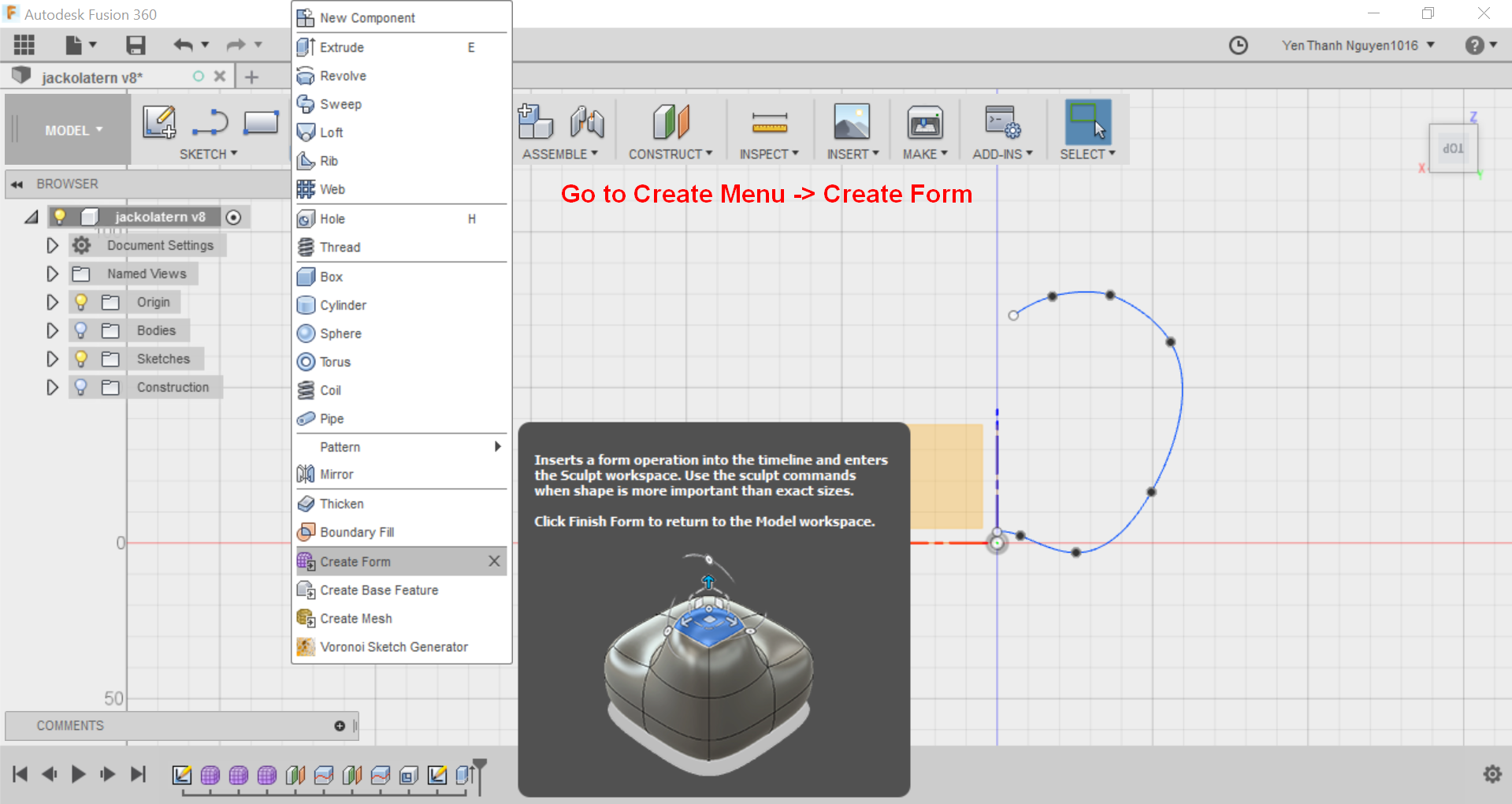
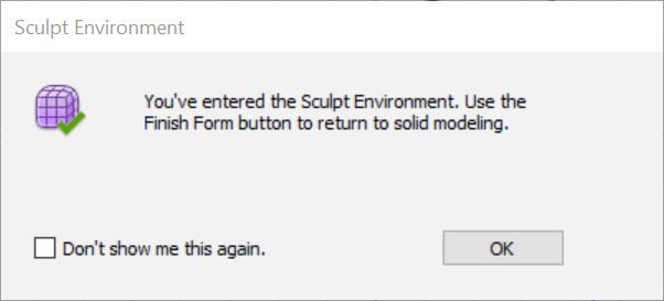
Next, I have to create a form for the pumpkin out of this outline by going to CREATE menu and select Create Form. At this point the software warns me that I am now going to the SCULPT environment.
When I am already in the SCULPT environment, I would like to revolve the curve that I sketched just now in order to make a 3D form from it. For this we go to the CREATE menu and then select Revolve.
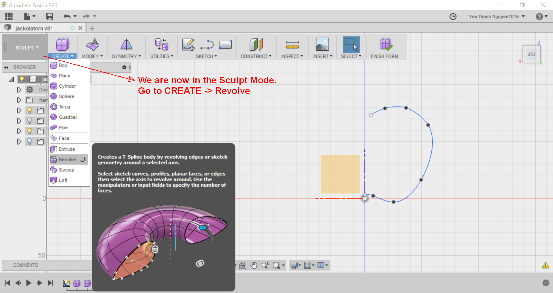
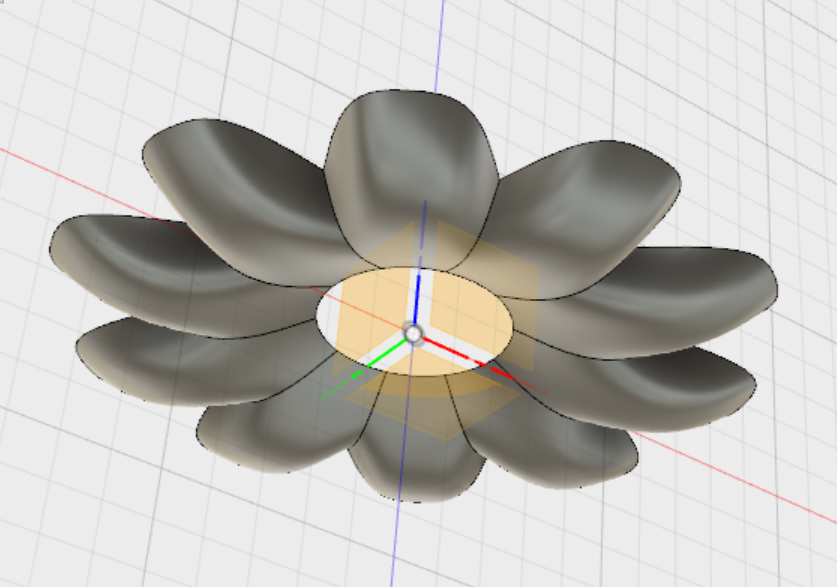
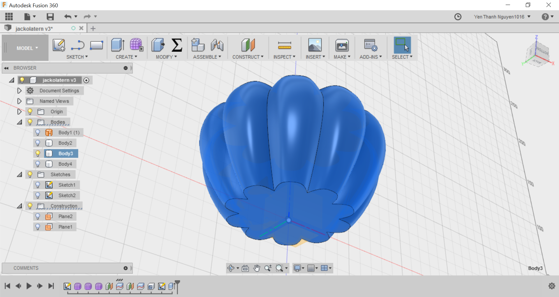
Now the software shows me a menu with the parameters for Revolve. For the Profile I choose the curve that I sketched, for the Axis I choose the vertical axis of the sketch's plane, the Spacing should be Curvature, the Symmetry type should be Circular, and the number of faces can be freely chosen depending on how many cloves of the pumpkin we want. For my design the parameters are chosen as below:
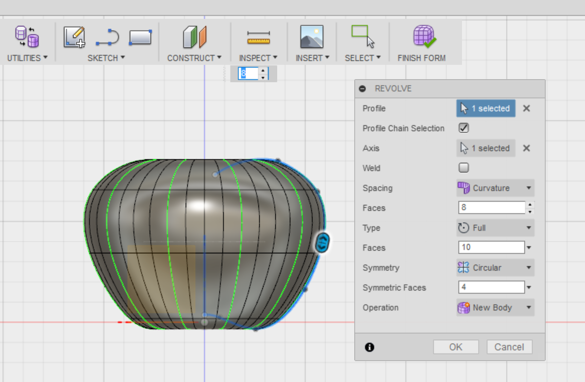
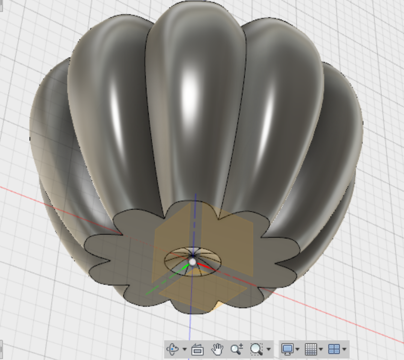
We can see that even before we press the OK button, we already have a preview of how the object will look like at the end of the Revolve process. When I press the OK button to confirm, I have a rough form of the pumpkin like this, with 10 equal faces on the surface of the pumpkin:
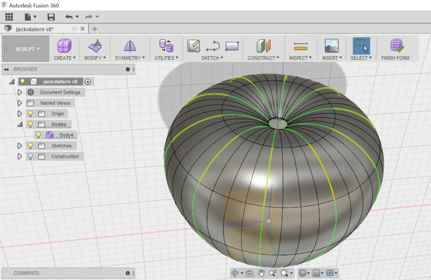
Also notice that now if I select one of the line segments of the pumpkin's surface, all the segments symmetrical to it are also selected (highlighted in yellow). This is because Symmetry constraint have been automatically turned on at the end of the Revolve process. For now I need this symmetry constraint so I will keep it, and I will clear it later.
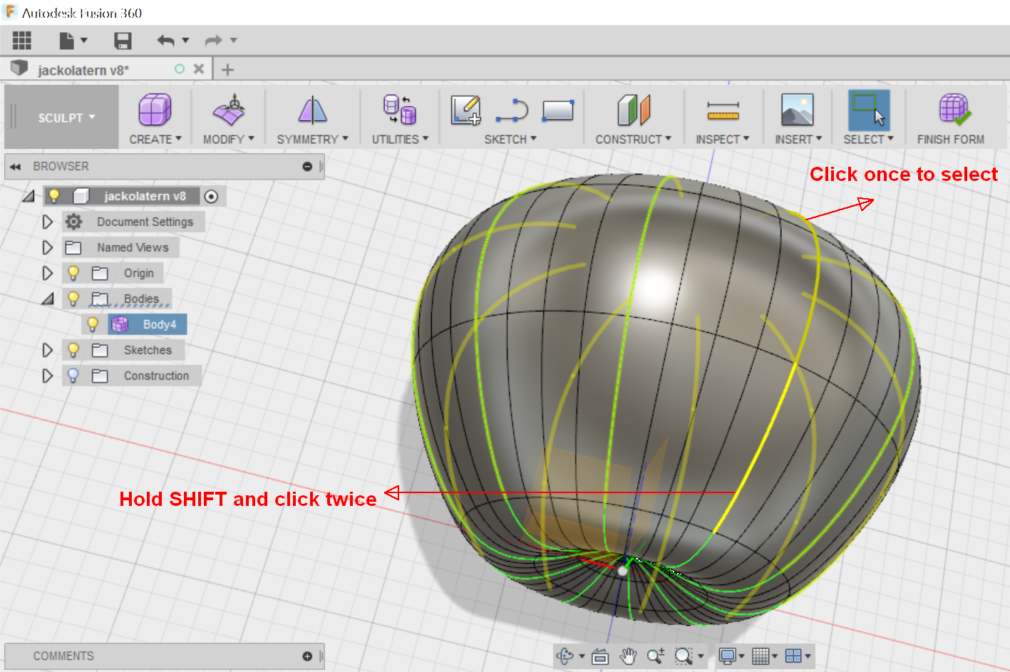
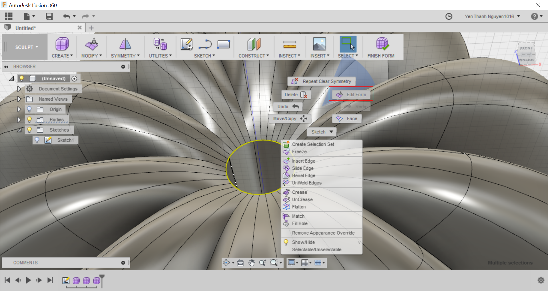
Now I need to select all of the curve segments on the pumpkin's surface (these are called T-Splines in Fusion 360) that I need to make a crease inwards, so that it actually looks more like a pumpkin. To do this, I have to click once on one of the curve segments at the top, then hold SHIFT and click twice on the curve segment at the bottom that lie on the same curving egde. Holding SHIFT and clicking twice means that all curve segments in between the 2 selected segments will also be selected.
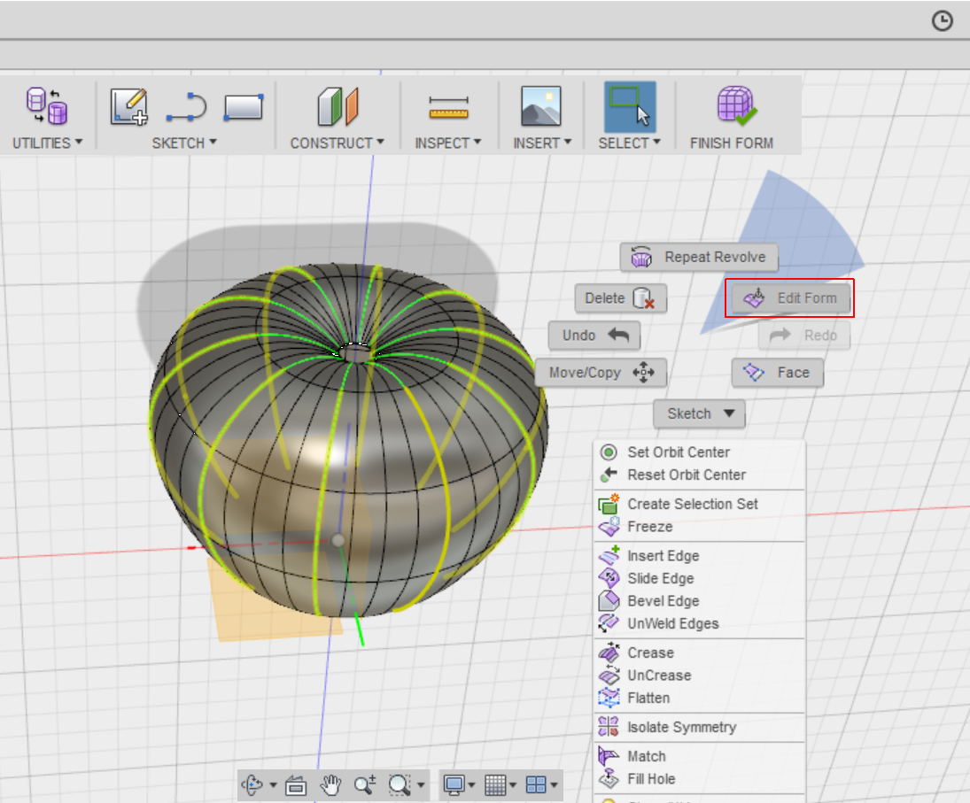
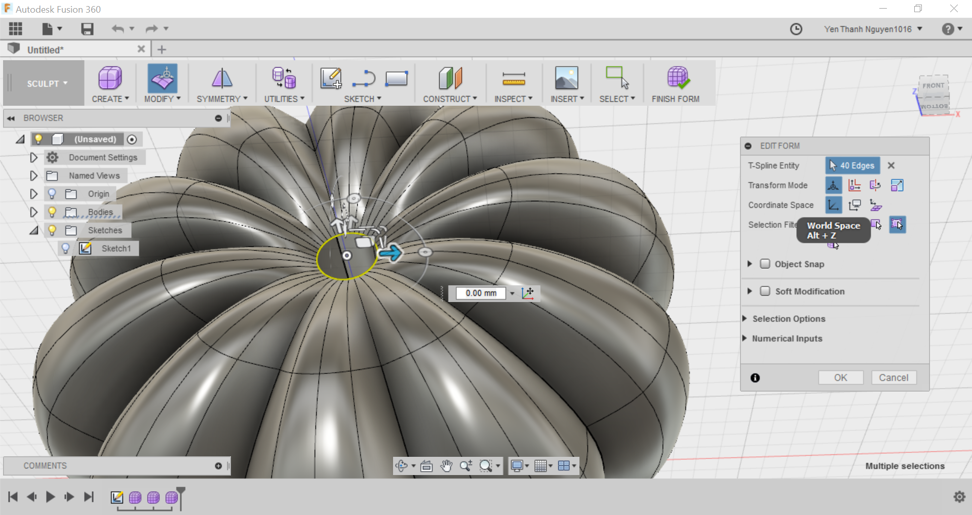
Now that all of the T-Splines are selected, I press right click to bring up the Options menu, then select Edit Form. I also change the perpestive to the FRONT plane in order to have better view of what I am doing next.
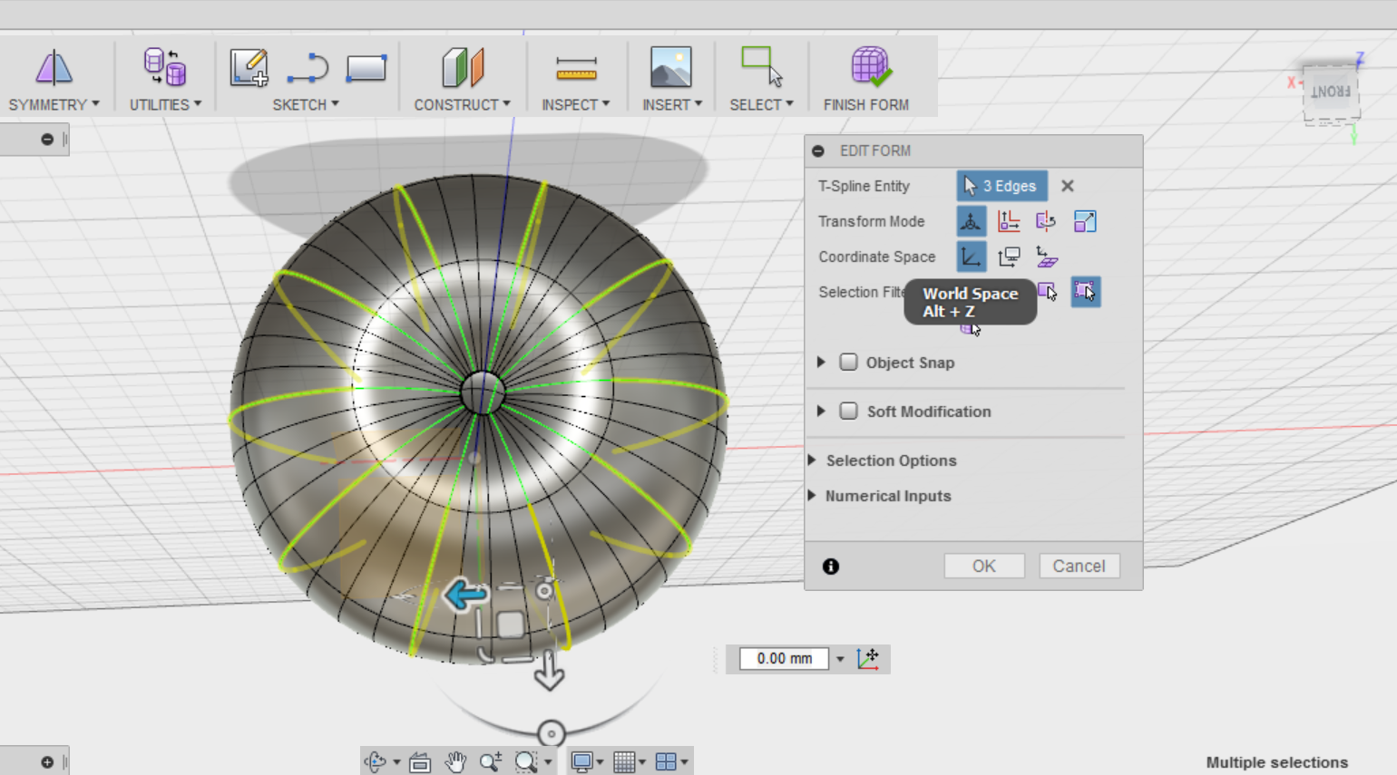
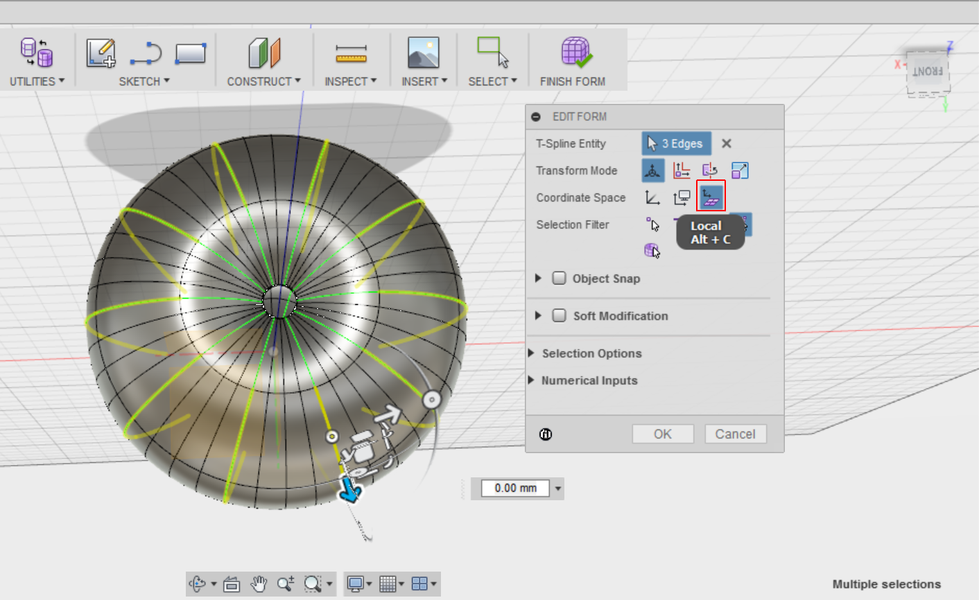
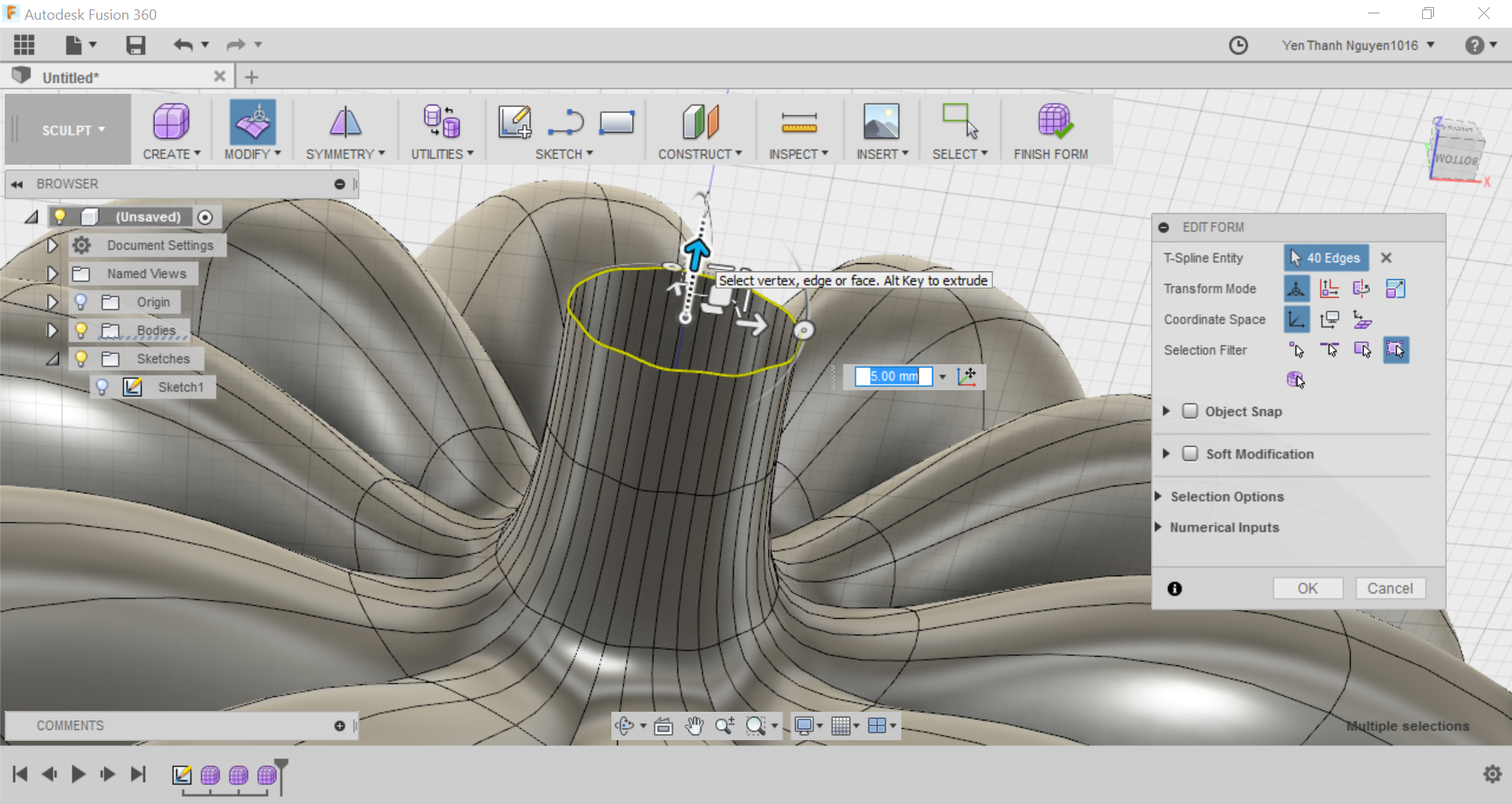
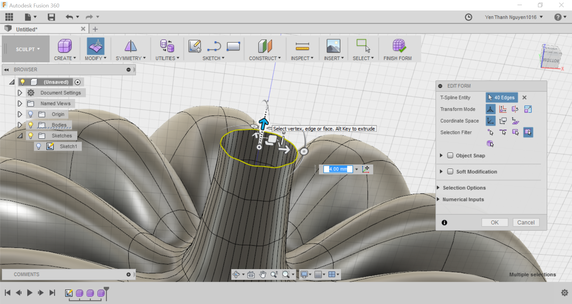
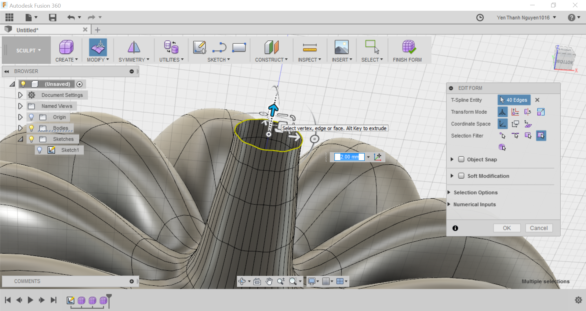
Now comes the fun part: FORMING THE PUMPKIN. In the parameters menu I have to first select Local as the Coordinate Space. This will change the coordinate system and the origin point from the global space (World Space) to the local space of the selected objects. Notice the difference in the coordinate system between the capture above and below:
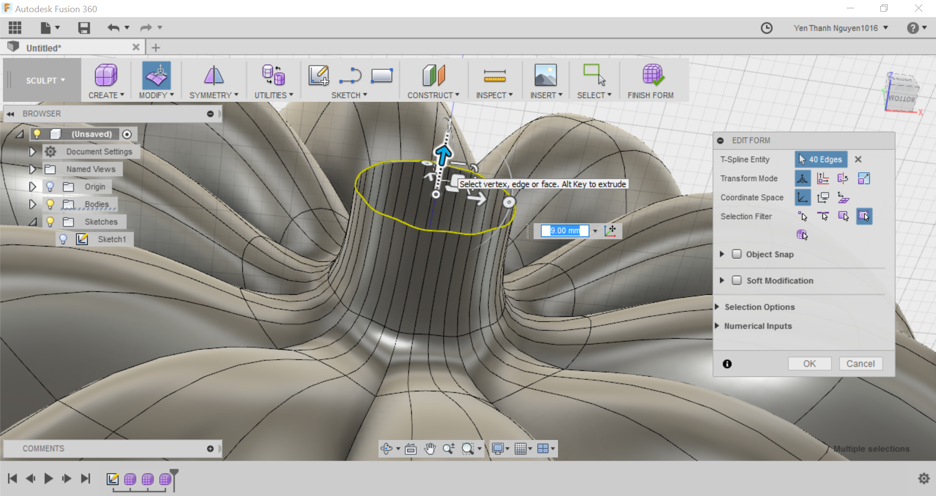
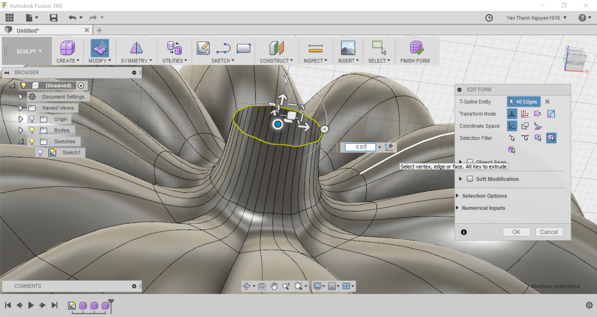
Next, I grab the arrow that is perpendicular to the yellow highlighted curves, so that the arrow is now highlighted in blue. Then I drag the arrow inwards (towards the inner of the pumpkin) to make a crease, or I can simply type in a value for the crease's depth. In this case, the number I put in has a negative value because I want the crease to be inwards, which is the opposite direction with the arrow's direction.
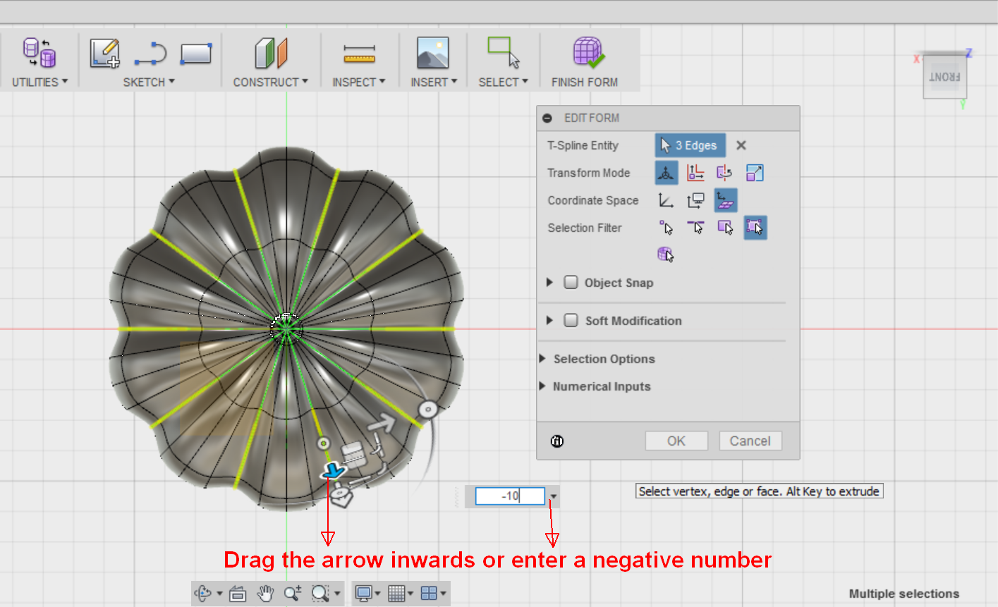
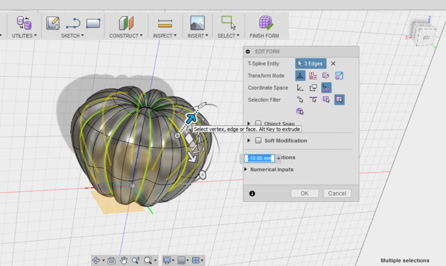
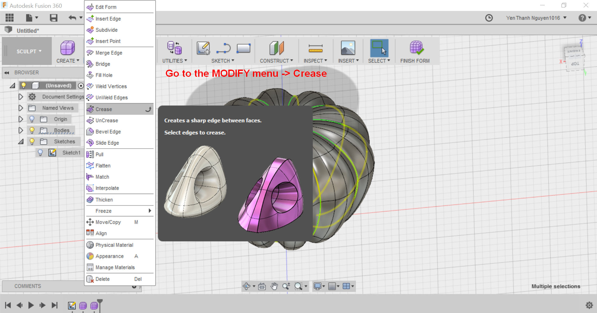
I press OK after getting the desired depth. Now, without deselecting the curves, I can make them more pronounced by going to MODIFY menu and select Crease. This will automatically sharpen the edges between the faces.
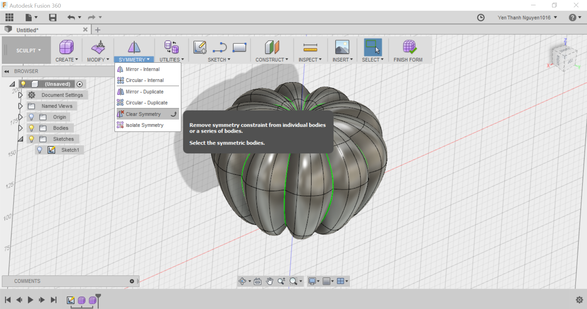
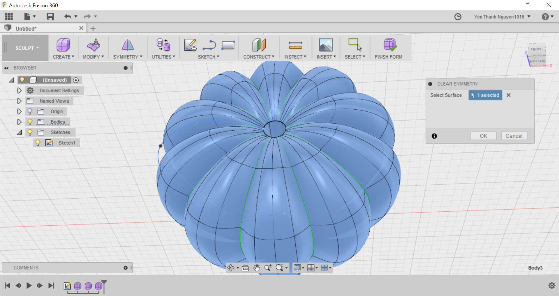
Also now I can remove the Symmetry constraint because I do not need it anymore. This is done in the SYMMETRY menu, under the option Clear Symmetry. I select the object and click OK to remove the symmetry constraints from the object.
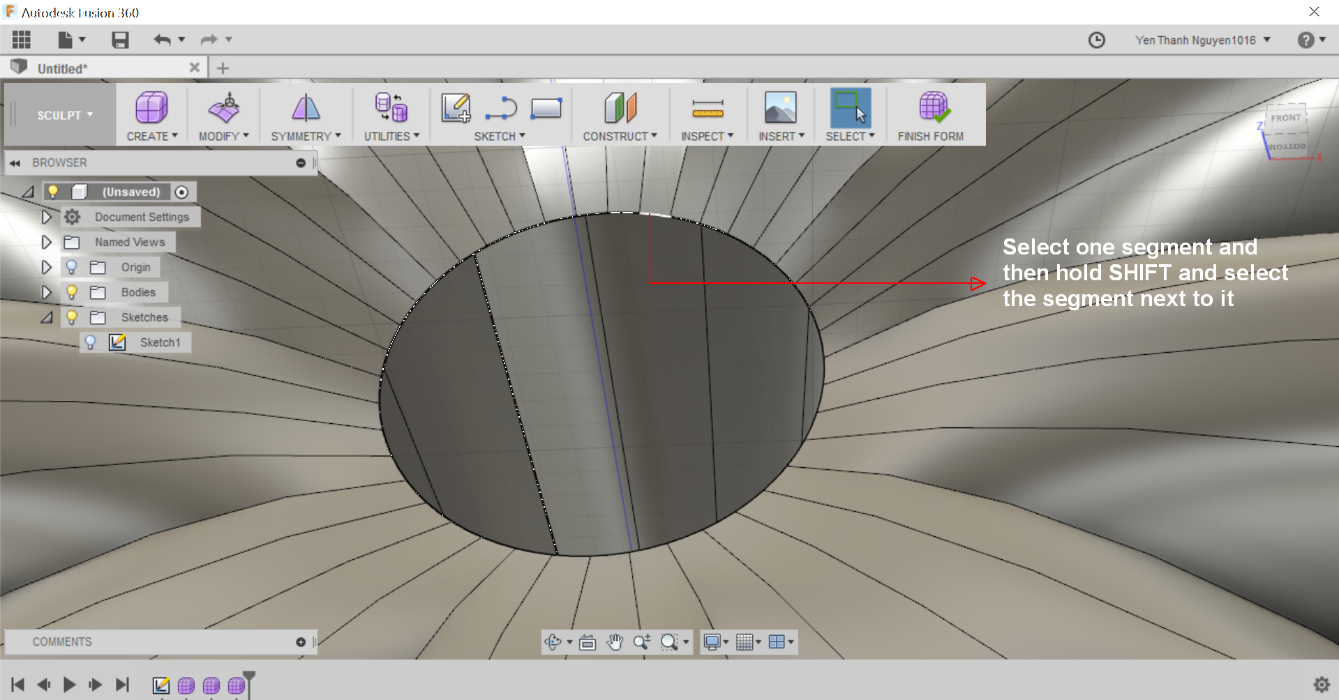
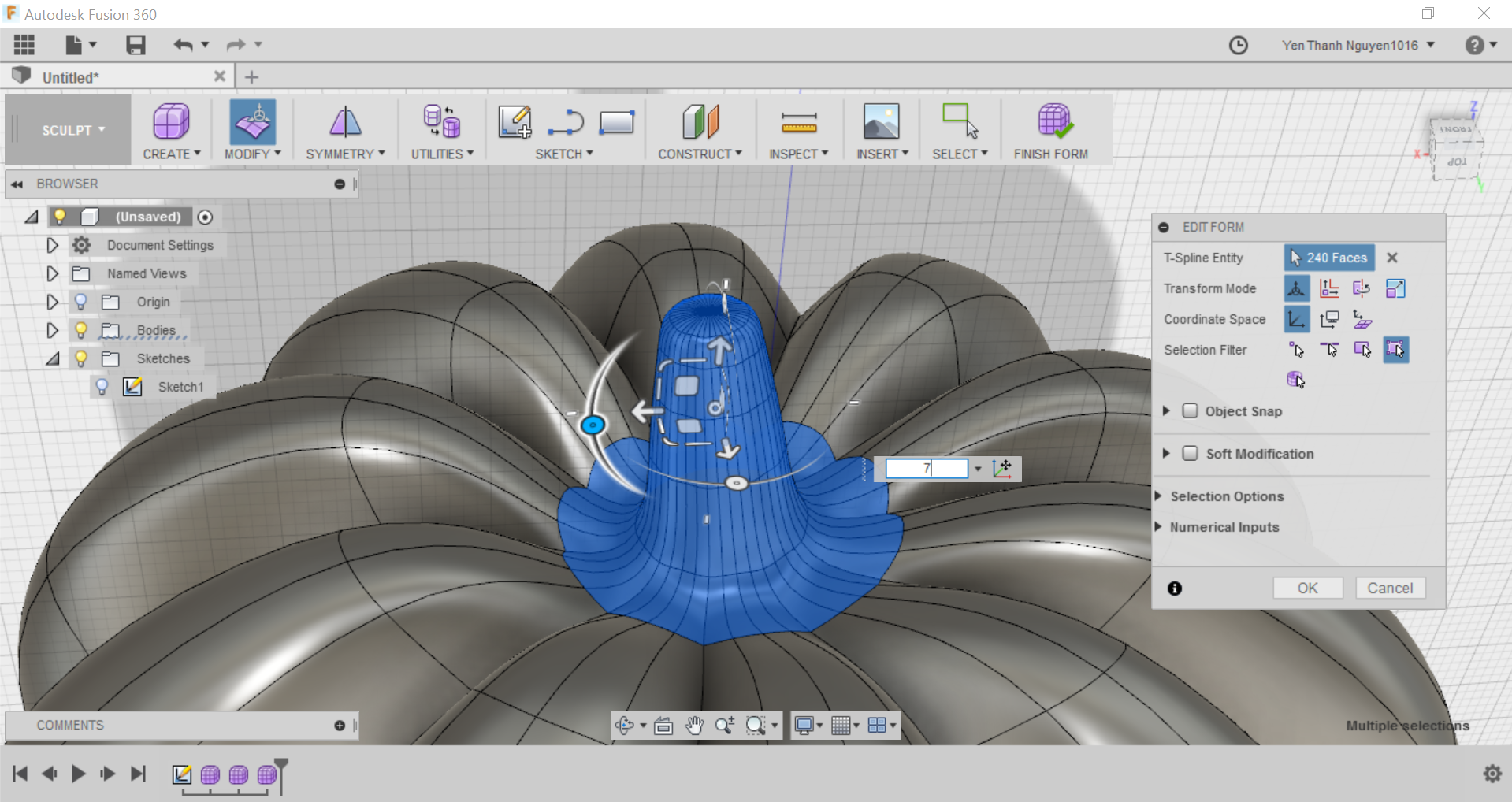
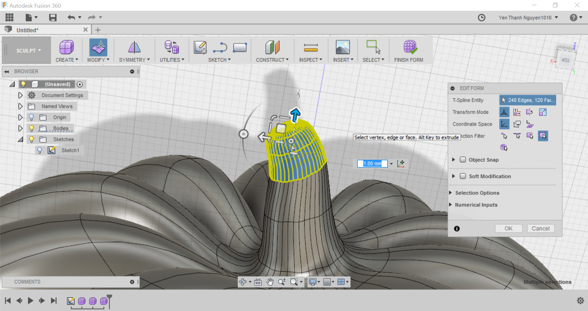
Now I proceed to form the stem of the pumpkin. I want to select all of the curve segments making up the hole at the top where the stem should be. To do this, I select one of the curve segment and hold SHIFT, then select another curve segment right next to it.
When the whole closed curve is selected (as highlight in yellow), I bring up the Option menu by right click once and choose Edit Form.
At this point I have to switch my Coordinate Space back to World Space.
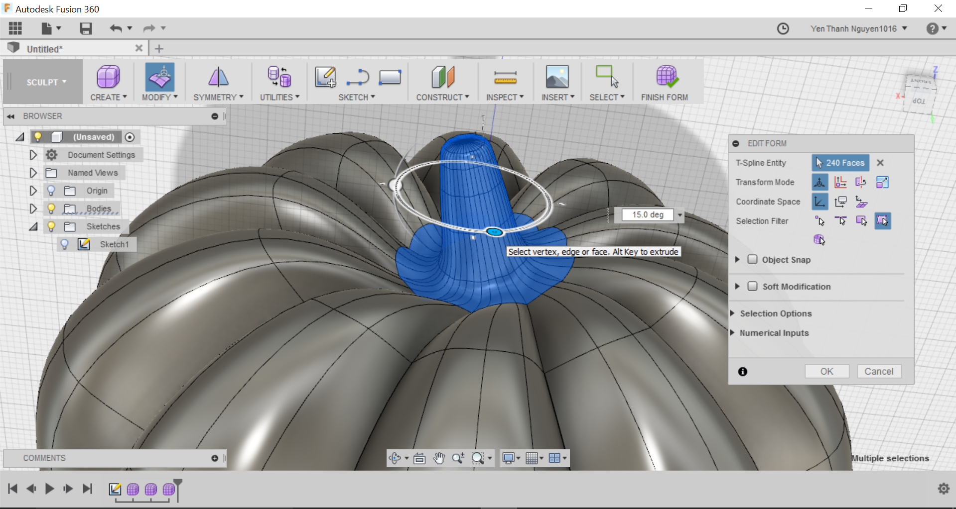
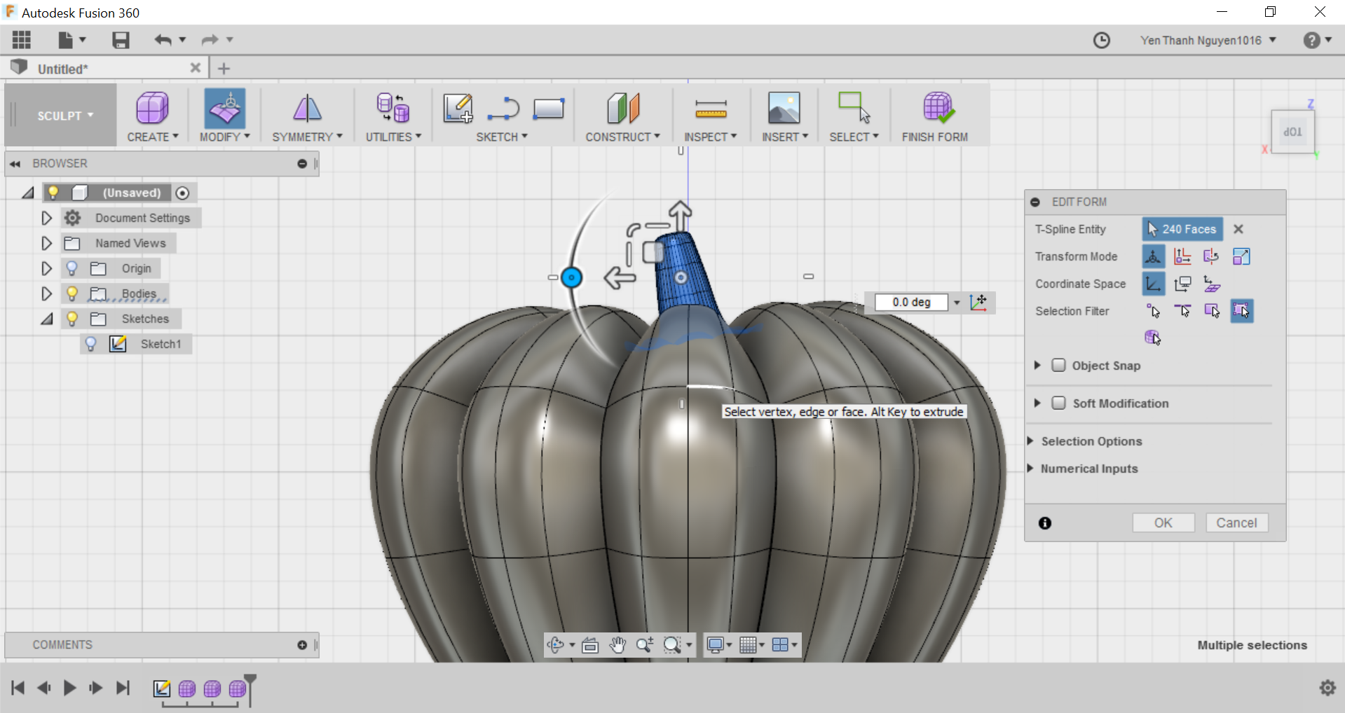
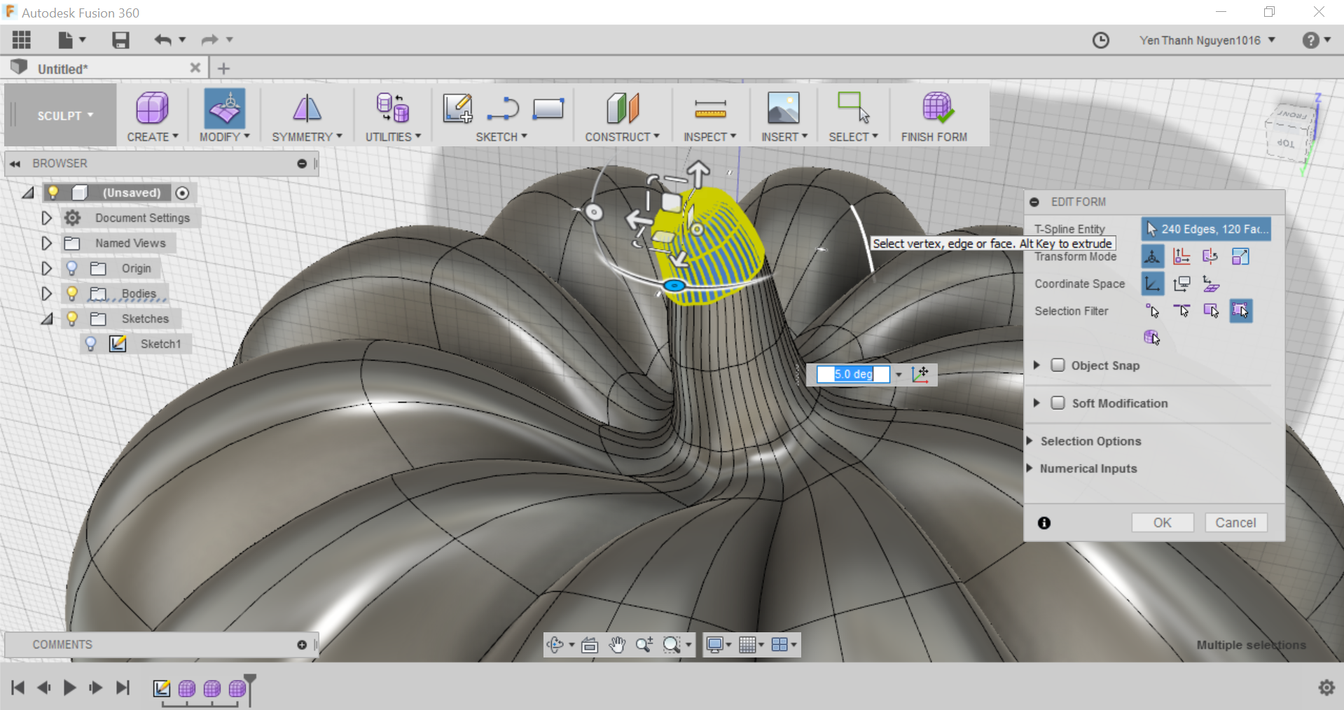
Now comes the challenging part: FORMING THE STEM. First, I hold the Alt Key, then grab the Up arrow (highlighted in blue), and drag it up to a desired height without releasing Alt Key.
When finish extruding, I grab the Scale Tool (the circle in the middle now highlighted in blue) and drag the mouse down in order to scale the stem down, or I can type in the scaling factor in the field. The scaling factor should be smaller than 1 for scaling down, and greater than 1 for scaling up.
I repeat the process of extruding and down scaling a few more times until I get the desired length and shape for the stem.
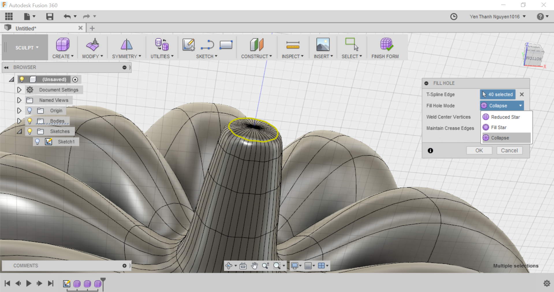
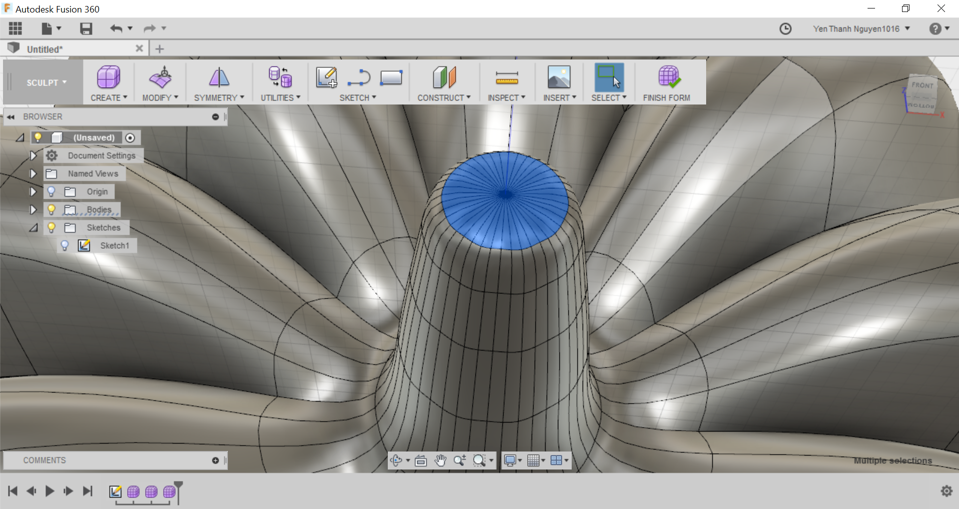
Finally I have to close the hole at the top of the stem by going to the MODIFY menu and select Fill Hole.
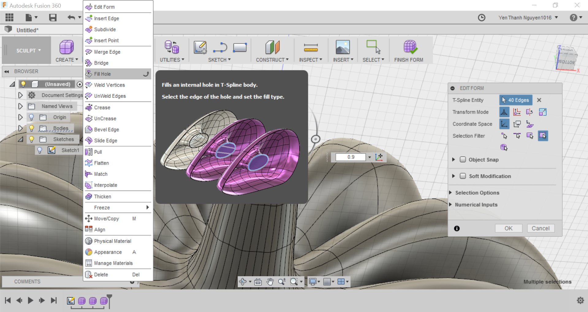
In the pop-up menu, I have to select Collapse as Fill Hole Mode.
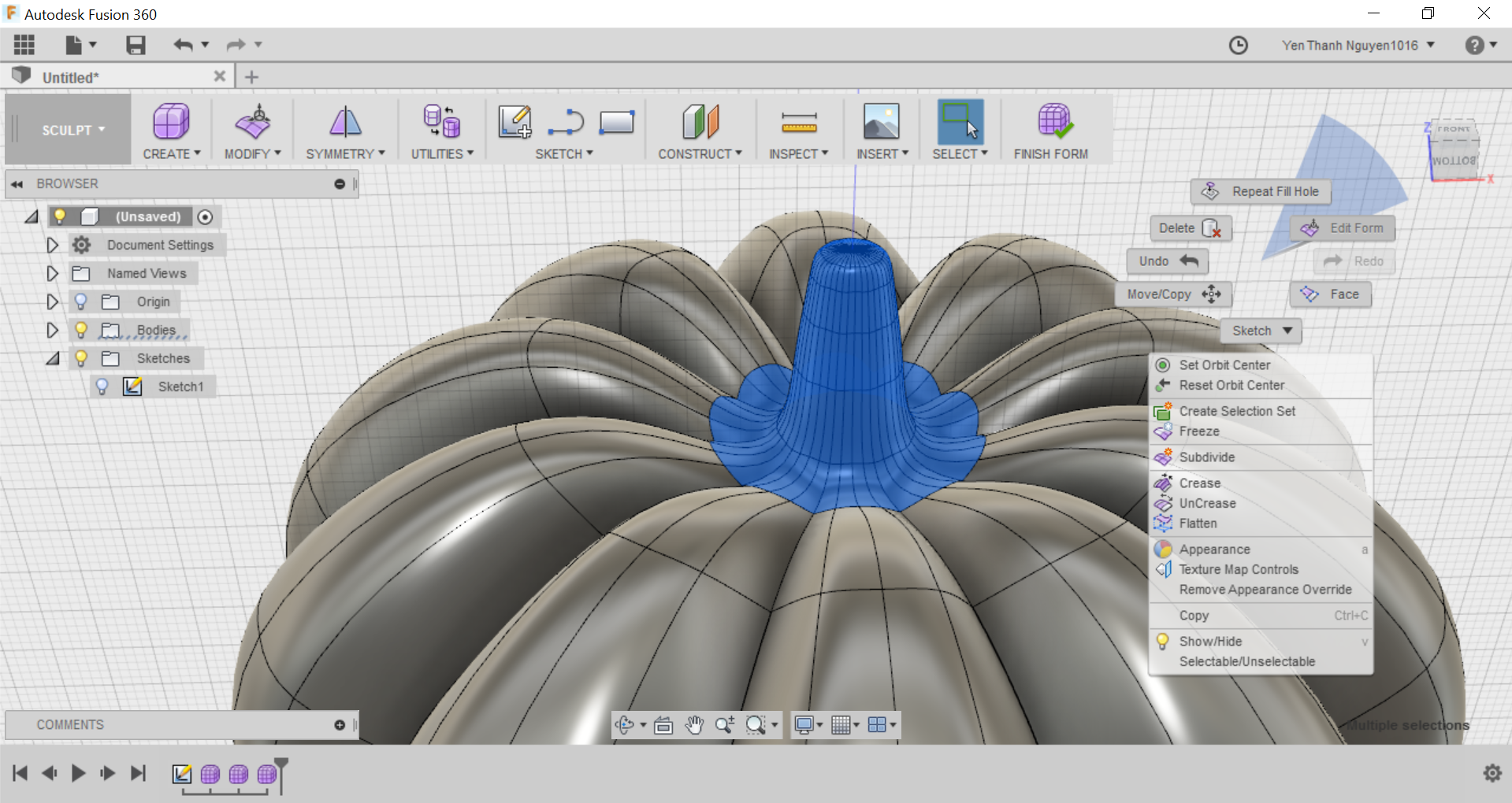
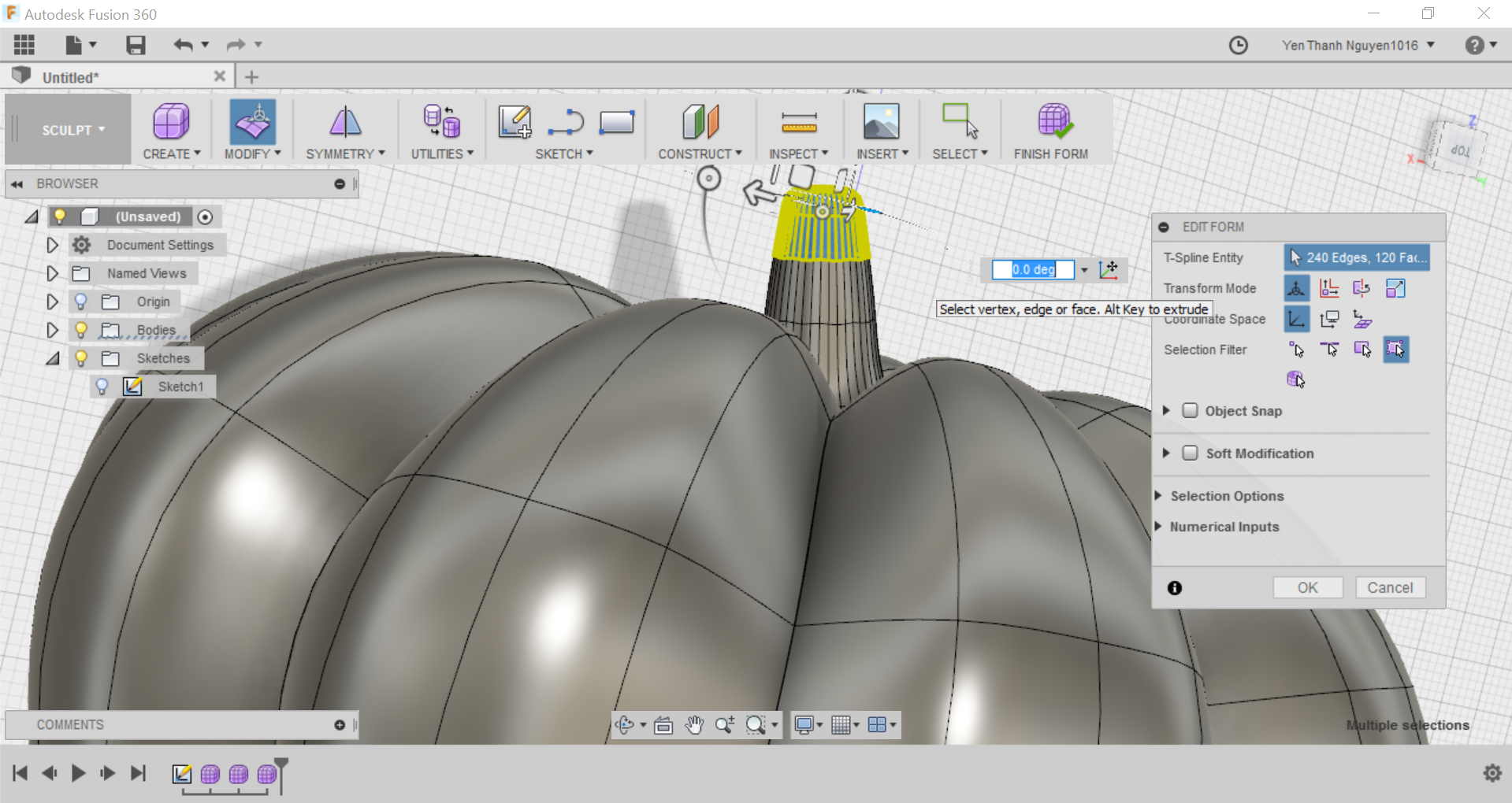
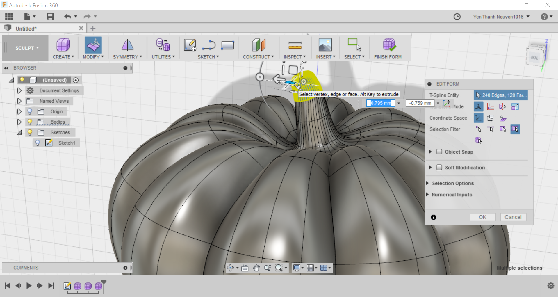
Next step is to edit the form of the stem so that it looks for realistic. In order to select the whole stem, first I use the same technique as before: select one face segment and hold SHIFT and select the segment right next to it.
From this point, I have to hold SHIFT and press the down arrow key on the keyboard a few times until the whole stem is selected. Then I right click and select Edit Form again.
First I would like to move the stem to the side instead of keeping it right in the center of the pumpkin. To do this, I grab the Translation Plane that is perpendicular to the stem (now highlighted in blue) and drag it around to give the stem the asymmetrical feel, or I can type in the translation distances in the parameter fields
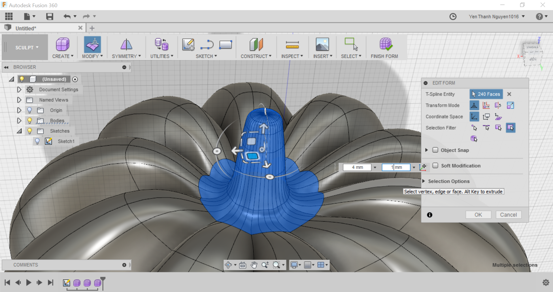
Next I grab one of the Rotation Axis (now highlighted in blue) and drag it to twist the stem, or I can type in the degree of rotation in the parameter field.
And also with another Rotation Axis, just to trying around how I can modify it.
And this is how the stem look from the side due to the rotation
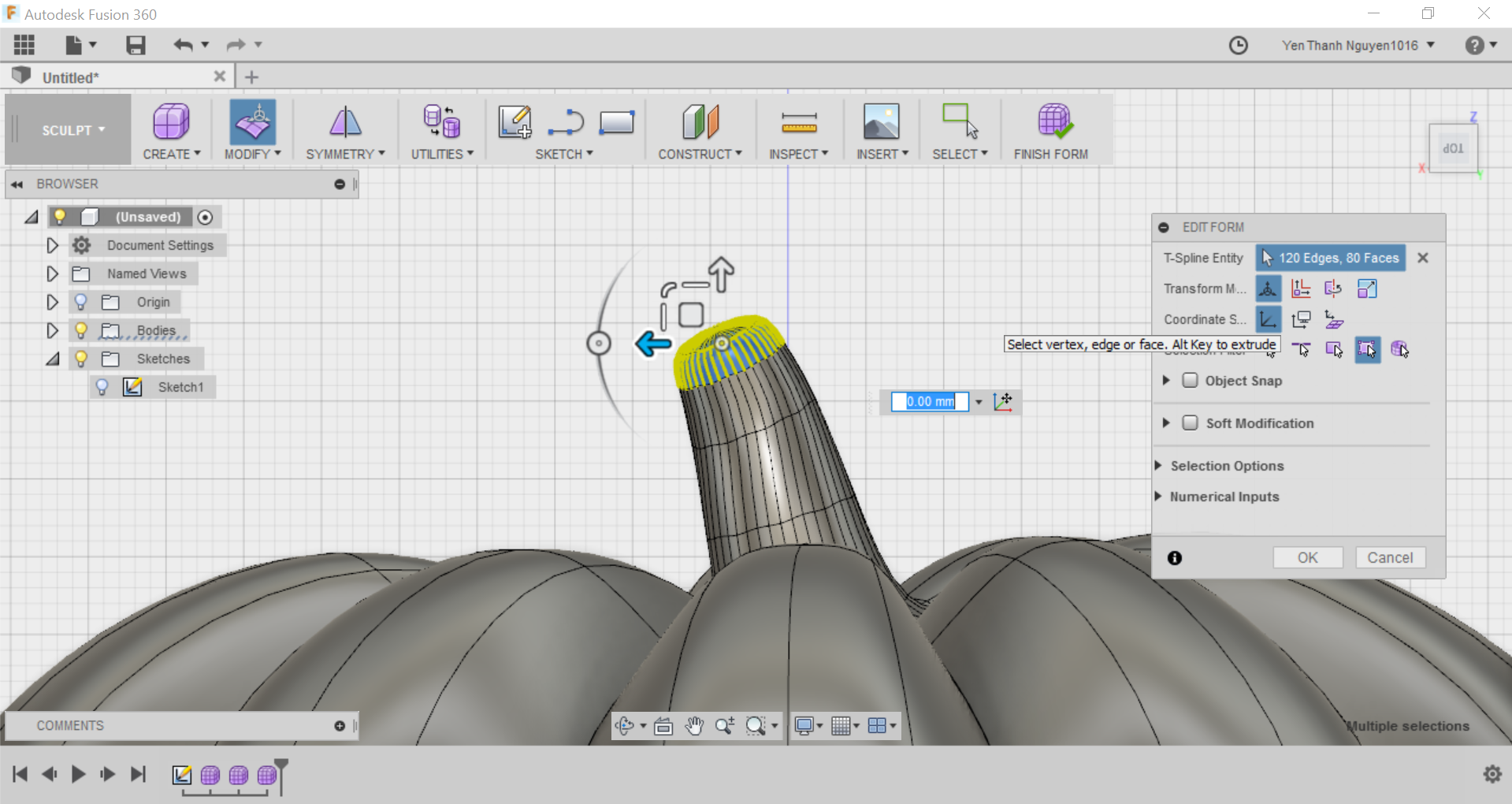
When happy with the translation and rotation of the whole stem, I repeat these steps for smaller parts at the top of the stem to give a more realistic look to the stem.
After modifying the stem, the pumpkin is already finished. Next is some decoration. In order to draw the "face" for the pumpkin, first I slice the pumpkin at the top and the bottom so I can draw a sketch uing the middle part, and also it is useful later for 3D printing.
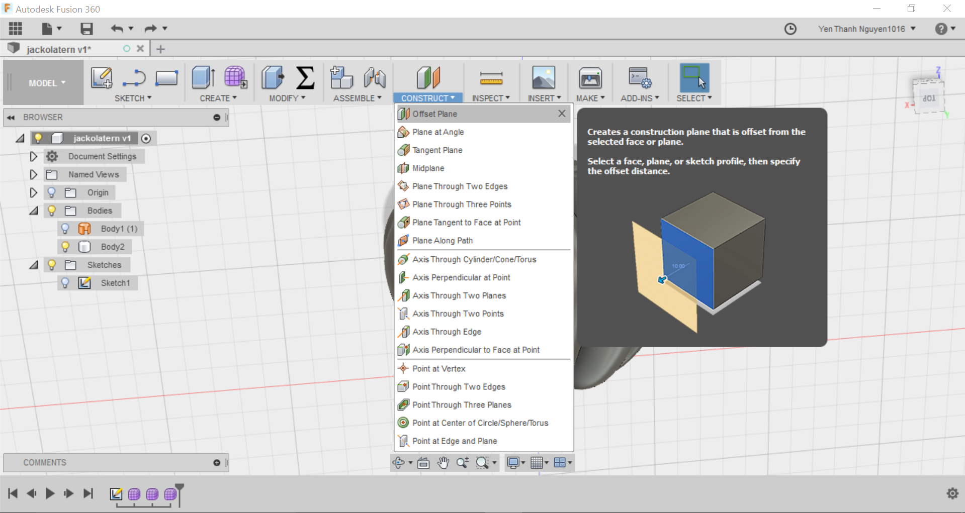
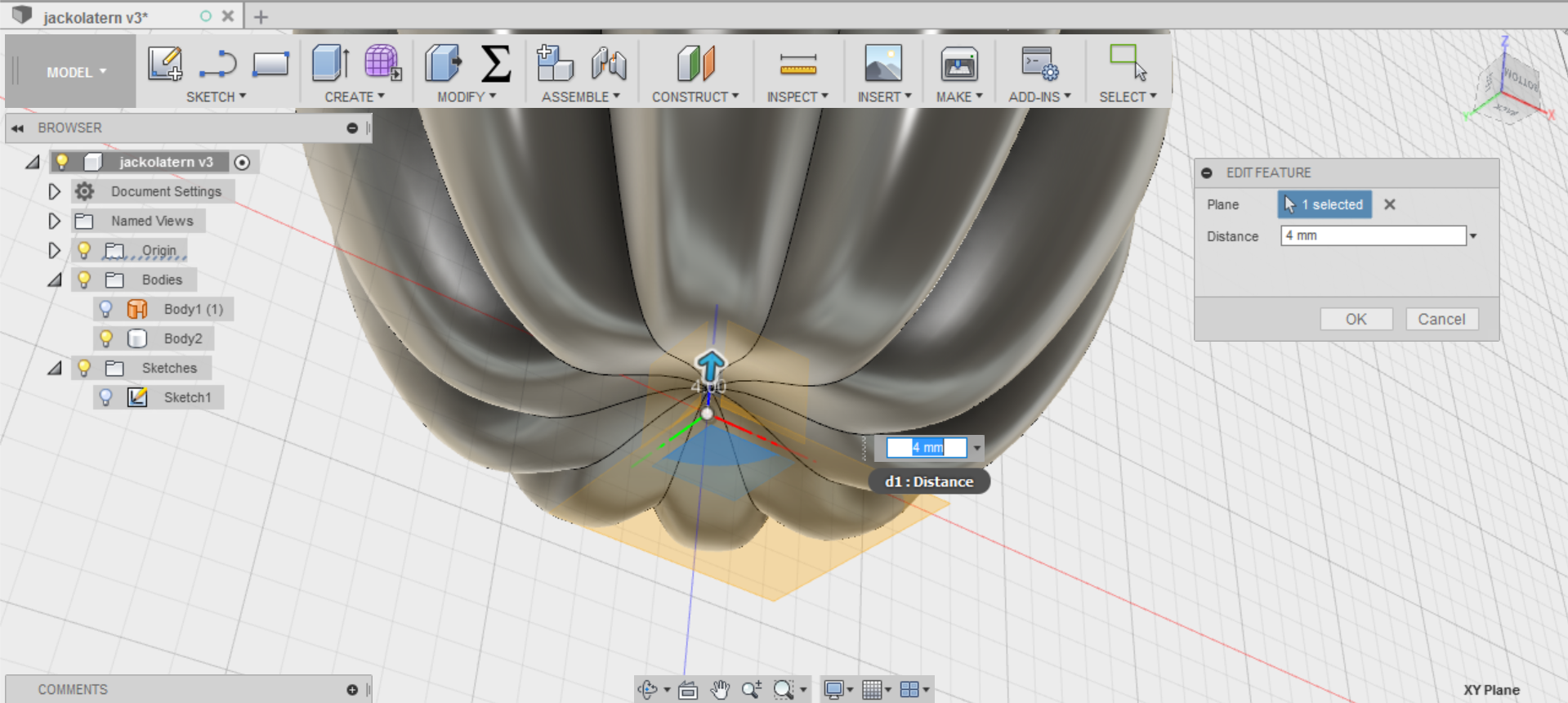
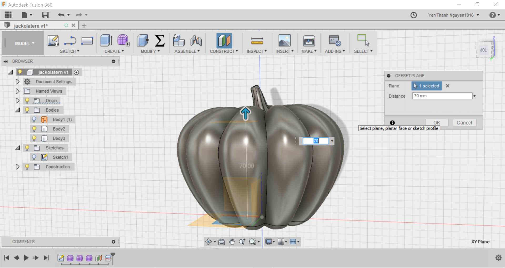
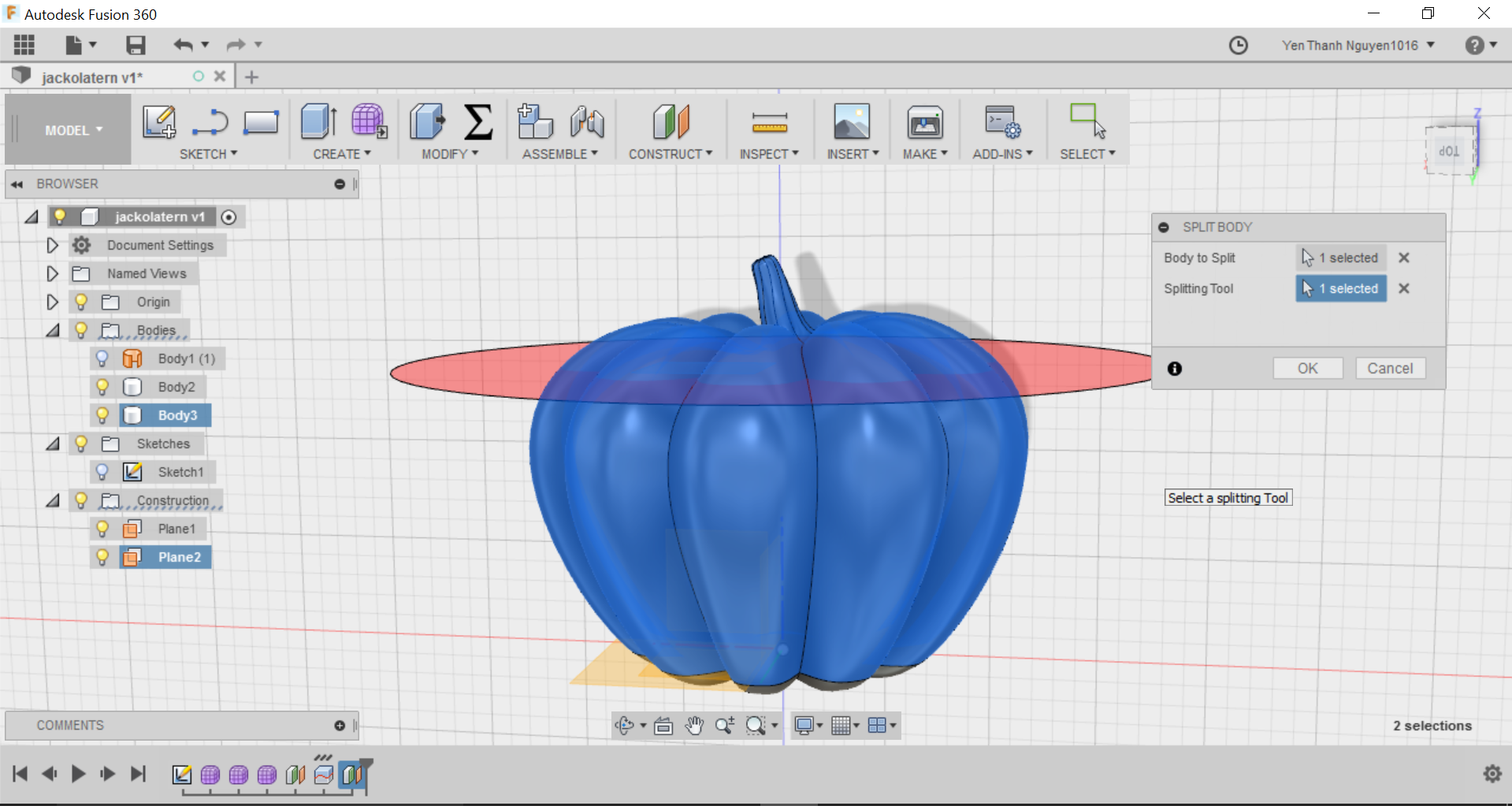
First I have define an offset plane to slice the pumpkin. I go to the CONSTRUCT menu and select Offset Plane.
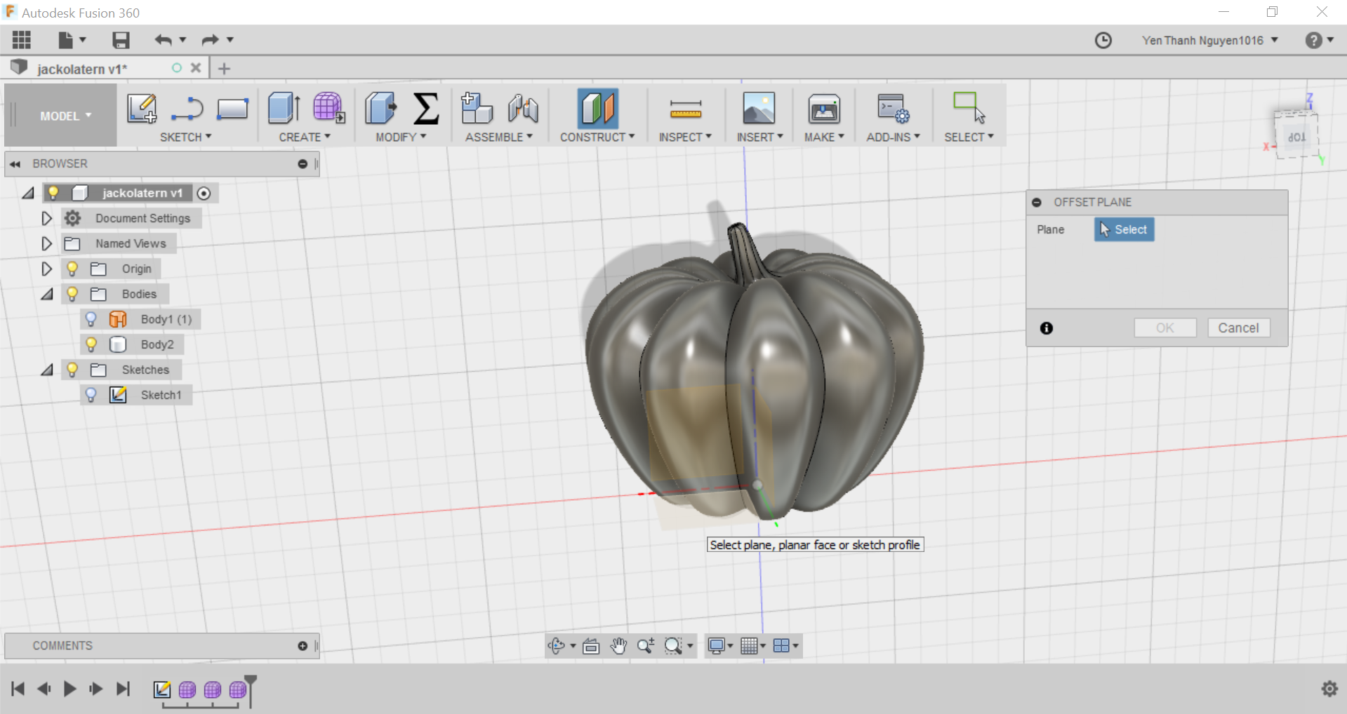
I select the XY plane which is perpendicular to the pumpkin's plane for the offset, and enter a small offset distance of 4mm, or simply drag the arrow upwards to the desired distance.
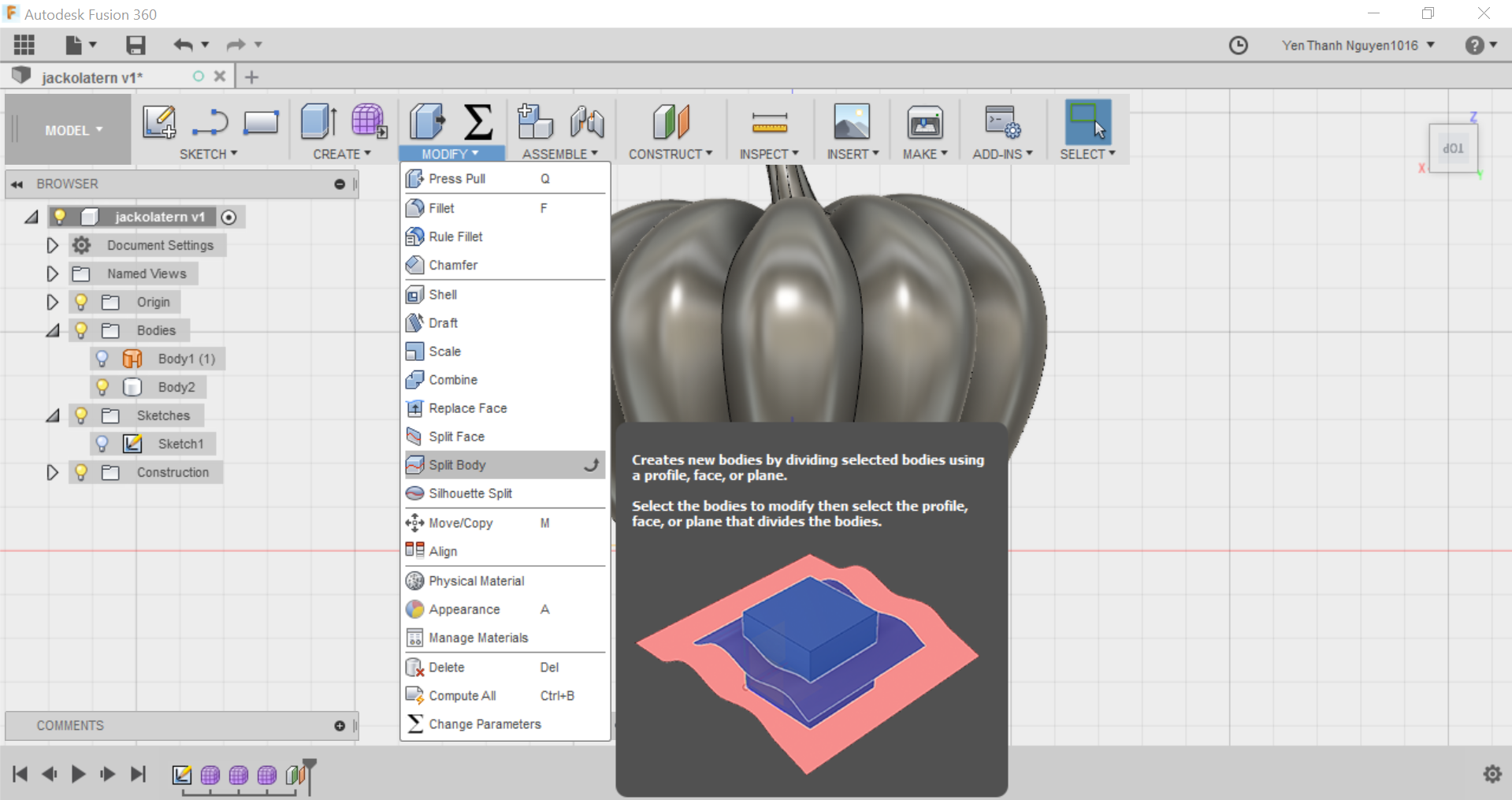
Then I go to MODIFY menu and select Split Body, choose the pumpkin as the Body to split, and the newly created plane as the Splititng Tool.
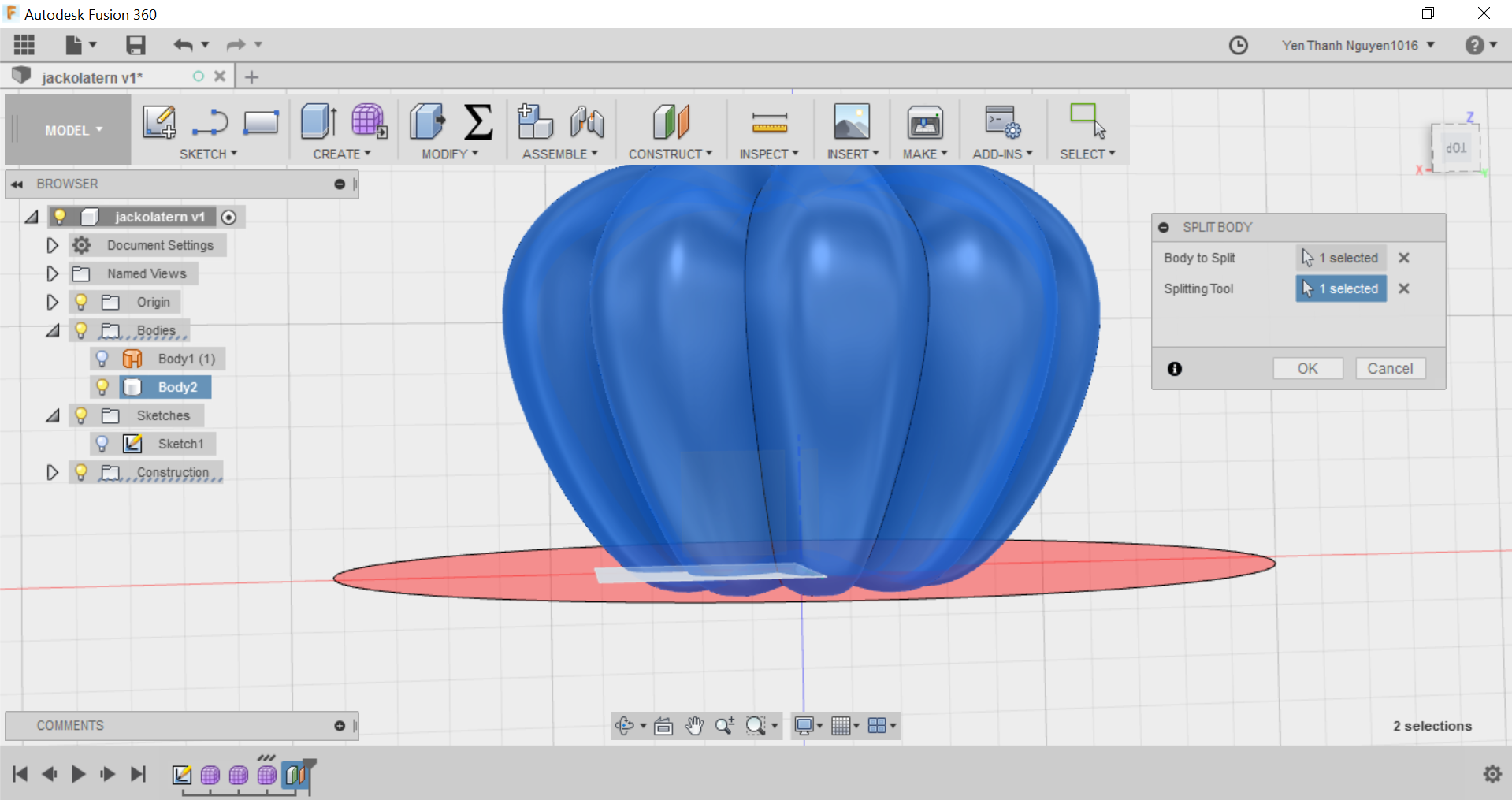
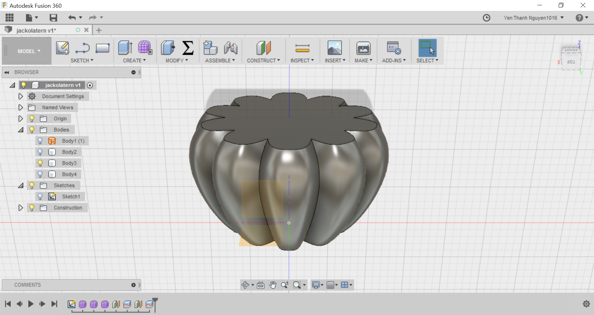
I repeat the same steps of creating an offset plane and split the body for the top part of the pumpkin:
So now I can hide the other parts of the pumpkin and show only the middle part.
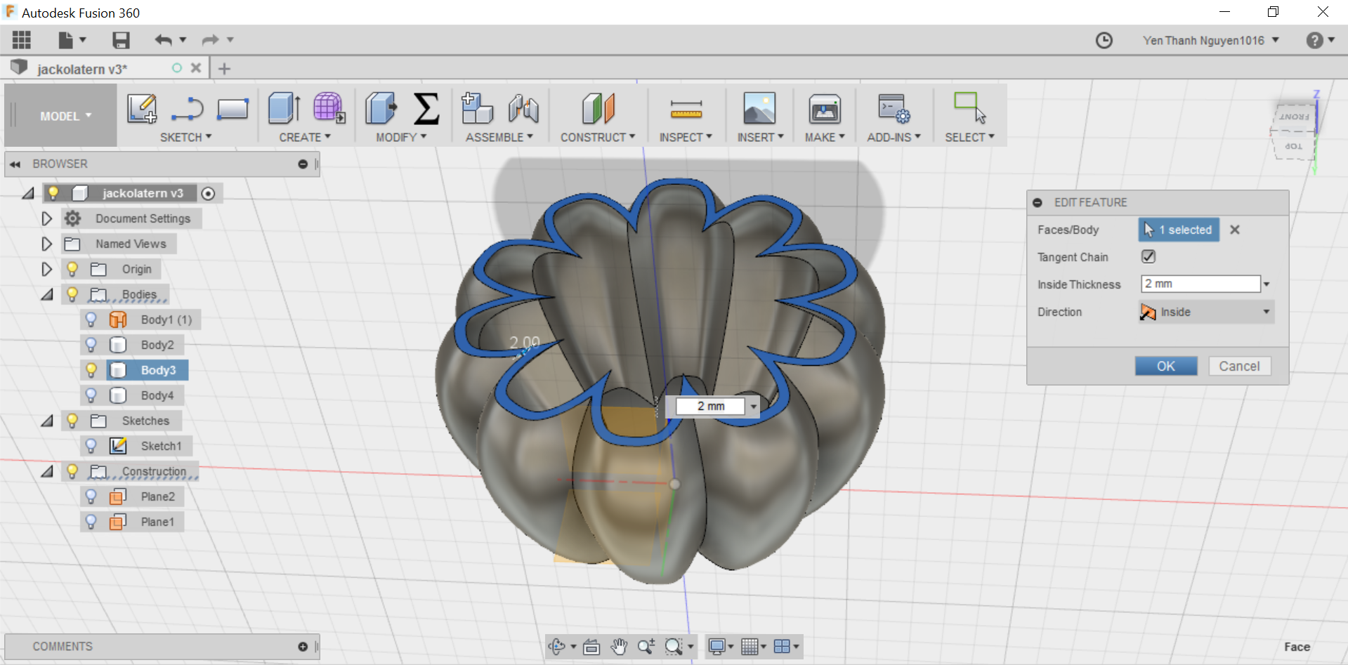
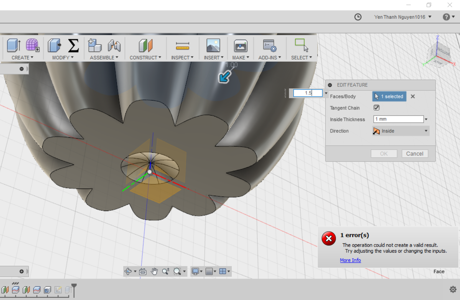
We cannot forget that the Jack-O-Lantern has to be empty inside, so it is time to "remove the flesh". I do this by going to MODIFY menu and select Shell.
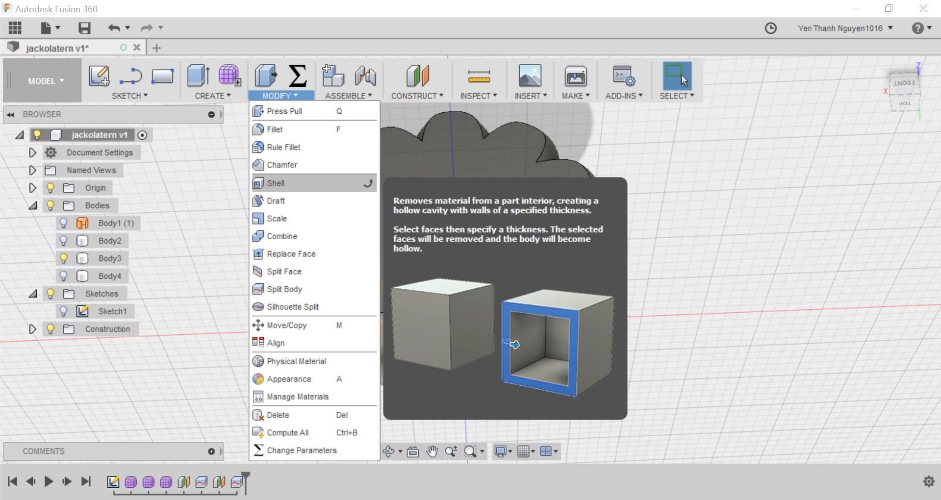
Here I can define how thick the shell of the pumpkin should be, and the Direction of shelling should be Inside.
Next I will start to sketch the "face" of the pumpkin in order to extrude it out from the shell. To have an idea how big my sketching space is, I will do a projection of the pumpkin onto the XZ plane (where I started the first sketch in the beginning). To do this, we press the P hotkey.
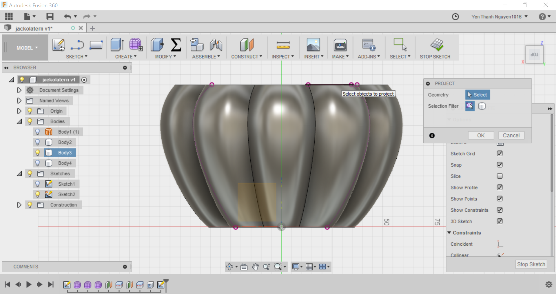
When the PROJECT parameters menu appears, I choose the outlines of the pumpkin as the Geometry to project and the XZ plane as the projection plane. When I press OK and turn off the visibility of the pumpkin Body, I should have the projection lines in purple. These give a boundary for my sketch. Now I can use the Line Tool and the Arc Tool to sketch one of the eyes, (half of) the nose and (half of) the mouth on the left side the pumpkin's projection.
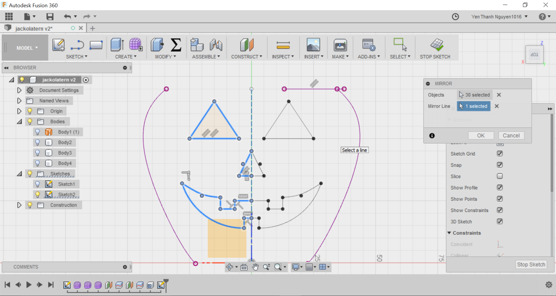
Now I will do a mirror over the vertical axis to complete the face. To do this, first I draw a line along a the vertical axis, and make it become a construction line by right clicking and choose Normal/Construction, or I can also use the hotkey X.
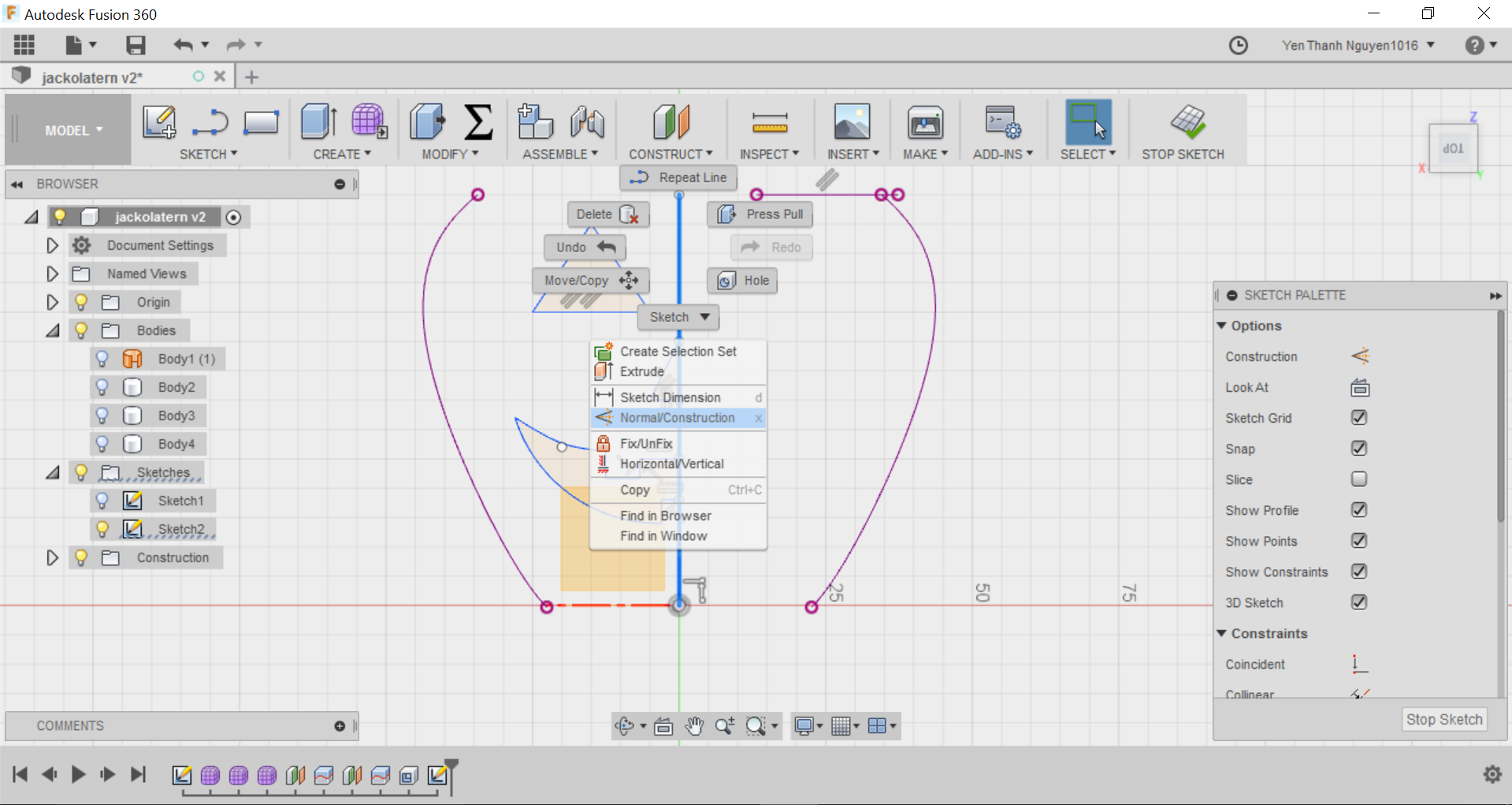
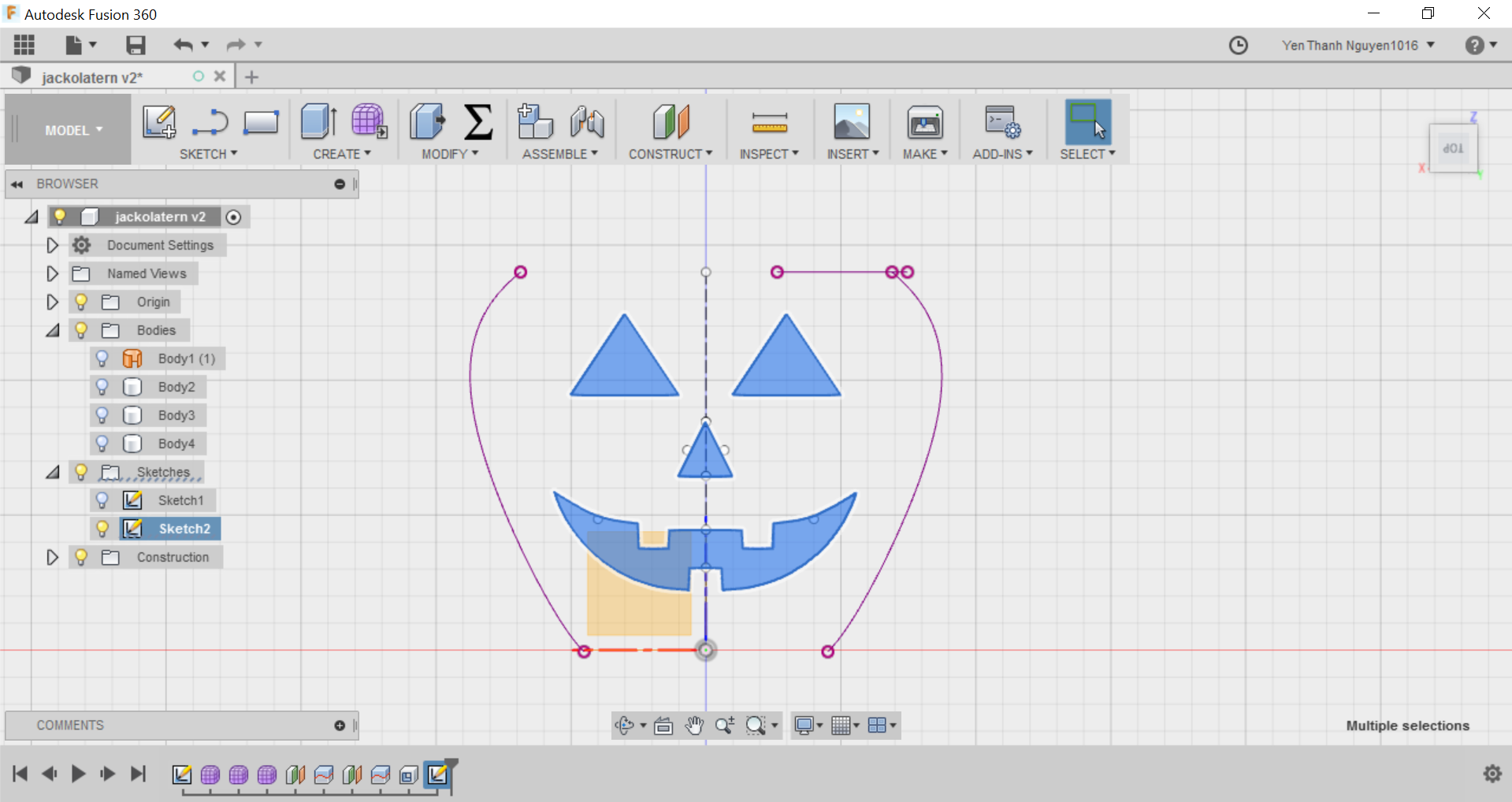
In the MIRROR parameters menu, I can choose the lines and arcs I have just sketched as objects and the construction line as the Mirror Line. So now I have the complate face for the pumpkin:
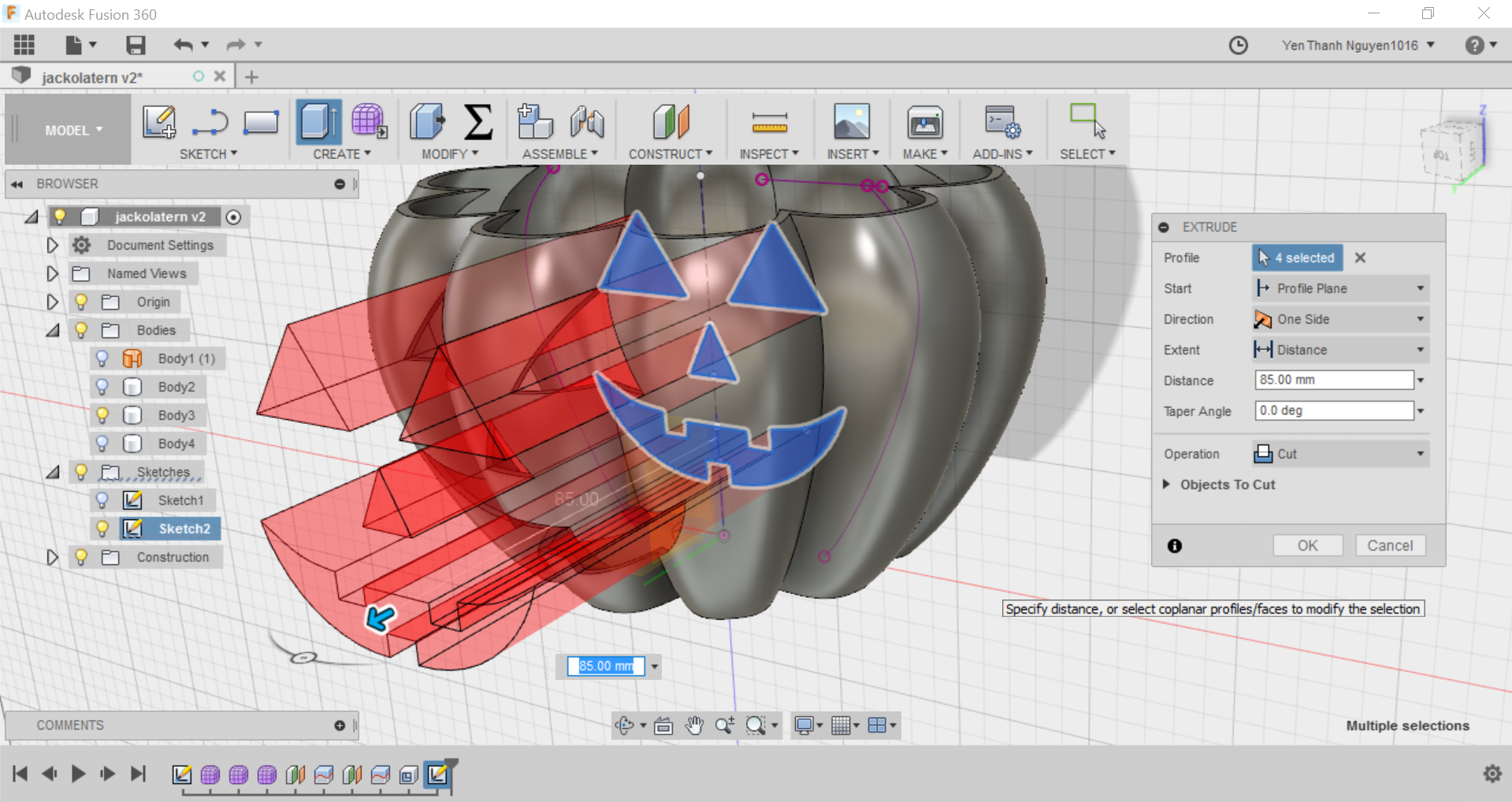
Then I select the parts of the face I just sketched and turn on again the visibility of the pumpkin Body to do an extrusion. I use the hotkey E to do this.
The Direction should be One Side and the Operation should be Cut. I only need to drag the mouse to a certain distance so that the extrusion fully cuts through one side of the pumpkin Body.
Now the Kack-O-Lantern is already finished, I just want to add some colors to it so it looks more "friendly" :D. To do this, I press the A hotkey for the Appearance menu to pop up.
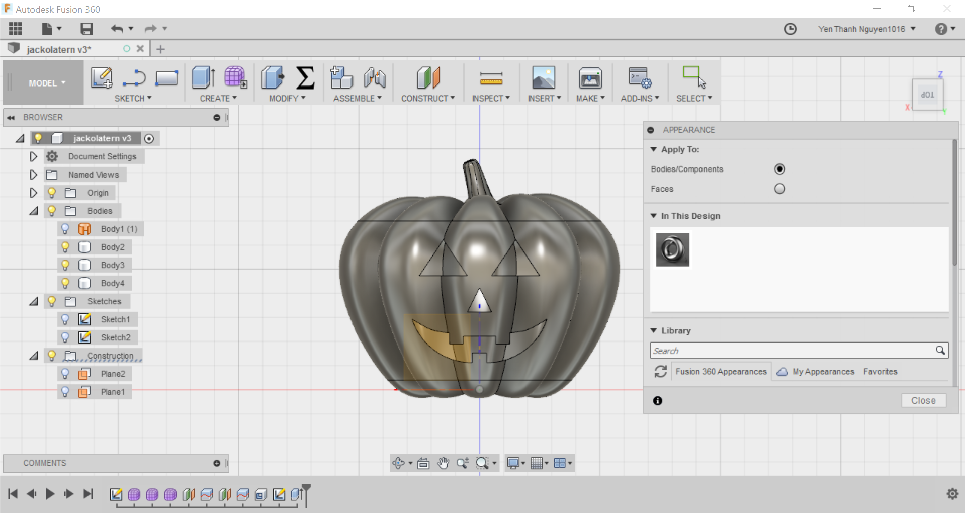
We can see in this menu that the current material is by default Steel. I would like to change the material to Plastic with color Yellow, so I select it from the Fusion 360 Appearance Library, and simply drag and drop the material on to the body.
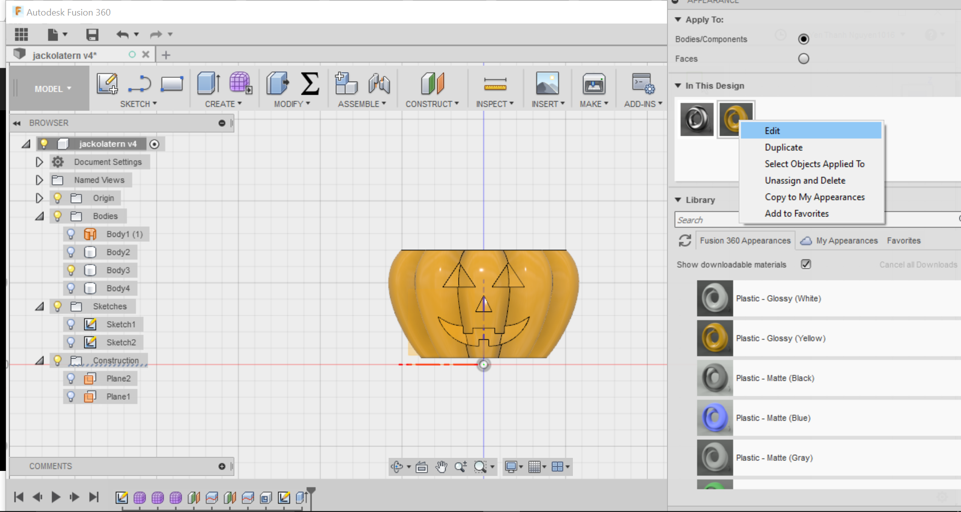
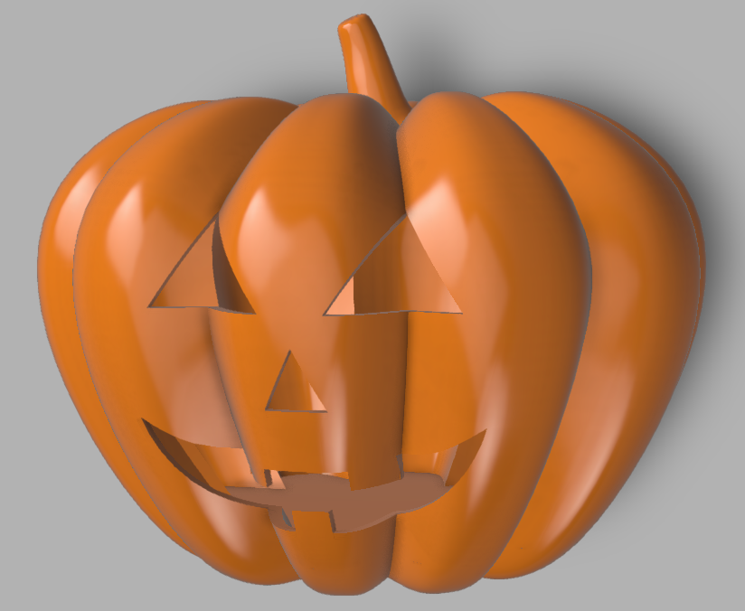
Finally, I would like to change the color of the material from yellow to orange because it is not readily available in the library. To do this, I right click on the material and choose Edit and choose orange from the Color Picker. Now I drag and drop this new material on to the other parts of the pumpkin body and my Jack-O-Lantern is fully decorated.
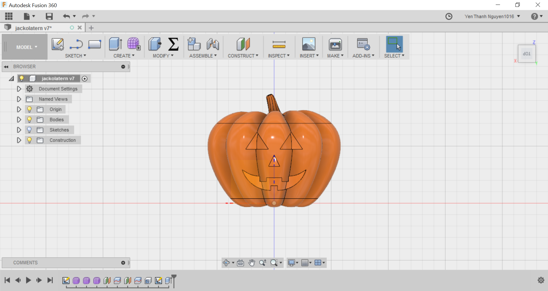
And this is how it looks in 3D:
The problem I encountered with my 2D design assignment was that sometimes the lines and curves do not intersect each other as expected, for example in this case it was like following:

Although this arc was not drawn from sketch but simply was duplicated using the PATTERN command, somehow it still did not join with the circle. As a result, I could not TRIM off unwanted line segments. Only when I zoomed in to fill the gap by extending the arc did the trimming work.
The 3D model of the Jack-O-Lantern looks simple but actually if we do not know some tips and tricks in the design process it could give some real headaches. From this tutorial, I learned that the flow of the design process has to be in a certain order so that the software can properly model what we intend to do. For example, I have to do the splitting of the full pumpkin body, not only so that later on it is easier to be 3D printed, but also in order to easily shell the pumpkin in the next step. If I do the splitting step after the shelling step, the bottom and top part of the pumpkin will also be shelled off, which I do not want because it will make the 3D print structure unstable.
Another problem I encountered also had to do with the splitting and shelling of the pumpkin. At the step of splitting the body with the offset plane, in the beginning I put in a too small value (in this case 1.2mm) for the offset and thus when the body is split, the 2 new bodies are not perfectly solid:
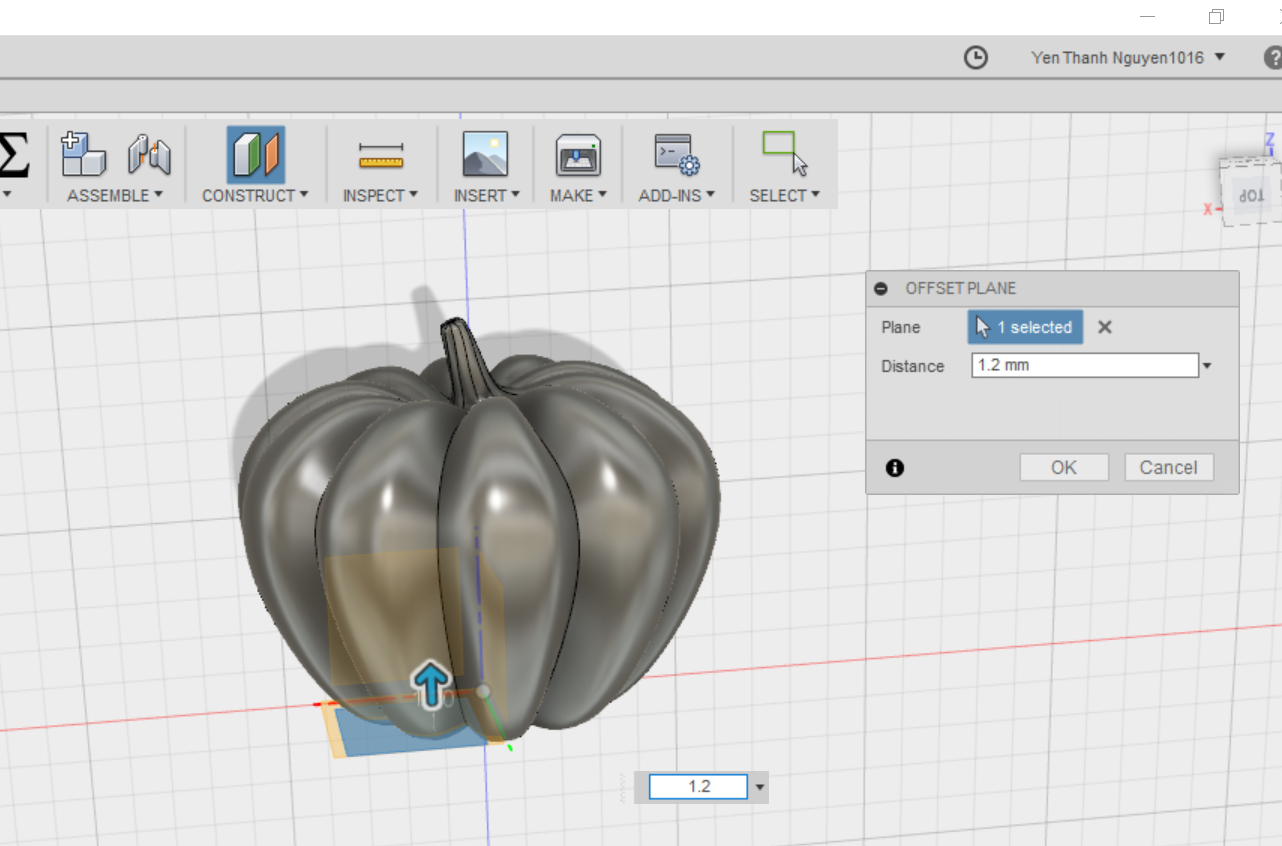
As a result, when I tried to shell the middle part of the pumpkin body, the software gave me an error:
Thus I had to edit my offset plane and bring it more upwards so that the bottom and the rest of the pumpkin are splitted in a solid way, like what we see in the end:
The DXF file for my 2D design - Mechanical Iris - can be downloaded here.
The Fusion 360 file for my 3D design - Jack-O-Lantern - can be downloaded here.